


CONTENT
A) Overview
B) Things used in this project
1. Hardware Components
2. Software, apps and online services
3. Hand Tools and Fabrication machines
C) Building
1. Coding the NodeMCU board
1.1- Adding and selecting the ESP8266 board to the IDE
1.2 – Downloading and adding necessary libraries
1.2- Coding the Sanitizer Dispenser and Temperature Scanner
2. IFTTT Setup
2.1- Getting WebHook Credentials
2.2- Creating an Applet
3. Coding the Bolt module
3.1 – Getting All the Credentials
3.2– Creating the conf.py file.
3.3- Creating the high_temp.py file
4. Schematics and Connections
4.1- PCB Designing
4.2- External Connections
5. Hardware
D) Demonstration
1. Testing the sanitiser dispenser and temperature detection.
2. Testing the calling and mail feature.
3. Flow Chart
4. Full Video
OVERVIEW
The device’s primary aim is to lower the spread of the coronavirus disease. The device checks for the person’s temperature. If it is under the usual temperature, there is a blue led which lights up indicates that the temperature is normal and the person can go. In case the person’s temperature is high, a red led lights up and a buzzer is activated to ensure that the person and the people around him are aware that he/she has a high temperature. Along with that, an automatic mail and phone call is placed to the owner or the person in charge of the place where the device has been set up. In addition to that, the system dispenses sanitiser automatically as soon as the person places his/her hand in front of the sensor. This prevents surface transmission, unlike the usual sanitiser dispersers.

THINGS USED IN THE PROJECT
HARDWARE COMPONENTS
- Bolt IOT Wi Fi Module
- GY-906 MLX90614-BAA Non-Contact Infrared Temperature Sensor
- Node-MCU/ ESP8266 Board (Any Arduino board would also work)
- HC-SR04 Ultrasonic Sensor
- 5V Submersible water pump motor
- 5V Relay Module
- 5mm LEDs – Red and Blue
- Copper Wires
- Jumper Wires (Male to Female, Male to Male) Female Pin Header Strip
- USB A to Micro USB Cables – 2
- Power Bank
- 1 m Plastic Pipe
- Plastic Box
- Custom Built PCB
SOFTWARES, APPS AND ONLINE SERVICES
- Bolt Iot Android App
- IFTTT
- Ubuntu (Vagrant/Virtual Box)
- Mailgun
- EasyEDA
- JLCPCB
HAND TOOLS AND FABRICATION MACHINES
- Soldering Iron (Generic)
- Solder Wire
- Glue Gun
- Hand Drill
- Wire Stripper
- Screw Drivers
BUILDING
1. CODING THE NODEMCU BOARD
In order to deploy our C++ code into the ESP8266 board , we need an IDE. For this, we will be using the Arduino IDE which can be downloaded from www.arduino.cc/en/software.
1.1 – Adding and Selecting the ESP8266 Board in the IDE
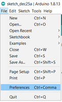
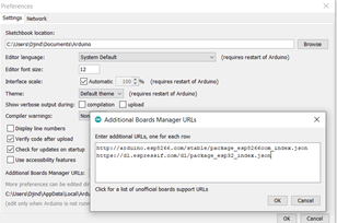
Before we jump on to coding the board, we need to make sure that the board is recognizable by the IDE. If you are using an Arduino board, you can skip this step but if you are using an ESP 8266 board, you will need to add it in the IDE. In order to do that, open the IDE and click on File >> Preferences and in the Additional Boards Manager URLs, add these 2 links separated by a comma:
http://arduino.esp8266.com/stable/package_esp8266com_index.json
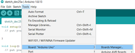
Until now, we have just added the URLs for the boards in the boards manager. To proceed further, we need to install it in the IDE. To install it, we first need to go to the Boards Manager by clicking on Tools>>Boards>>Boards Manager
Inside the Boards Manager, we need to search for esp8266 and install it.
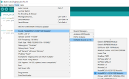
Once we do that, we need to select the correct board. In our case, it is the NodeMCU 1.0 board. To select it, go to Tools>>Board>>ESP8266 Boards >> NodeMCU 1.0
1.2- Downloading and adding necessary libraries:
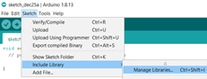
It is not only the board which needs to be recognized. We are using 2 additional sensors which are the ultrasonic sensor and the temperature sensor and we need to make sure that the board is able to communicate with it. For that, we need to install their libraries. The library for the Adafruit MLX90614 Temperature Sensor can be installed from the IDE itself. We need to go to Sketch>>Include Library>>Manage Libraries. In the Library Manager, search for the sensor and install its library.
Next, we need to install the library for the Ultrasonic Sensor. This library by Erick Simoes makes it really easy to use the sensor. Firstly, open THIS LINK and it would install a zip folder of the library into your system.
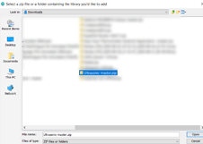
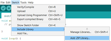
Then go to Sketch>>Include Library>>Add a .ZIP Library. Then an explorer window will open. Navigate to the location when the zip folder has been installed and select it.
1.3-Coding the Sanitizer Dispenser and Temperature Scanner:
Well, I guess this is the part you were waiting for. I am going to explain the code part by part . Please do pay attention to the comments in the code as well.
So firstly, before the setup function, we need to import the libraries and declare the pins and variables. That’s what we are doing here.
/* IMPORTING THE LIBRARIES */
#include <ESP8266WiFi.h>
#include <Wire.h>
#include <Adafruit_MLX90614.h>
#include <Ultrasonic.h>
/* DECLARING THE VARIABLES */
int distance; //variable to store distance measured by the ultrasonic sensor
float temp_f; //variable to store the temperature

/* NAMINGS THE PINS AS PER THE OBJECTS CONNECTED TO IT */
#define triger D3 //the trigger pin of the ultrasonic sensor
#define echo D4 //the echo pin of the ultrasonic sensor
#define boltpin D6 //pin connected to pin 0 of bolt iot module
#define relayofmotor D5 //Pin connected to the relay which will help in acivating the motor
#define greenled D7 //the led which I want to glow when the temperature is low
#define buzzerandredled  D8 //the pin which is connected to the red led and the buzzer which is want to activate of the temperature is high.
/*DECLARING THE SENSOR OBJECTS*/
Ultrasonic ultrasonic(triger, echo); //Creating an ultrasonic sensor object with the trigger and echo pins as the parameters
Adafruit_MLX90614 mlx = Adafruit_MLX90614();//creating a temperature sensor object
One question which might come up to your mind is that why have we declared the temperature variable as a float and not an integer. Well, it is because float is a datatype which can even store decimals unlike an integer. Because most of the times the temperature is a decimal number, I have used a float instead of an int.
Next, we move on to the setup function. All the code in the setup function is just run once in the start. This is where we declare of the pins are output or input and also do other basic things like starting the sensor.
void setup() {
  Serial.begin(9600);//Starting the serial monitor at 9600 baud
  mlx.begin();//starting the sensor
  /* DECLARING THE OUTPUT PINS */
  pinMode(relayofmotor, OUTPUT);
  pinMode(boltpin, OUTPUT);
  pinMode(greenled, OUTPUT);
  pinMode(buzzerandredled, OUTPUT);
}
Now we move on to the loop function. The code inside this function continuously runs.
void loop() {
  distance = ultrasonic.read(); //Stores the distance in cm  measured by in ultrasonic sensor in the variable
  temp_f = mlx.readObjectTempF(); //Stores the temperature in fahrenheit measured by in temperature sensor the variable
  if (distance<8){ // This set of code will run if the distance is less than 8 which means someone's hand is below the device

      if (temp_f>98.6 and temp_f<1500){ //person is in front of the sensor and temperature is higer than usual. Errors are also avoided as if the temperature value is 1500, it means there is an issue with the sensor.
      digitalWrite(boltpin, HIGH);
      digitalWrite(relayofmotor, HIGH);
      digitalWrite(buzzerandredled, HIGH);
      delay(1000);
      digitalWrite(relayofmotor, LOW);
      delay(1000);
      digitalWrite(buzzerandredled, LOW);
      delay(11000);
      digitalWrite(boltpin, LOW);
    }
    if (temp_f<98.5 and temp_f<1500){ // person is in  of sensor but temperature ok
    digitalWrite(relayofmotor, HIGH);
    digitalWrite(greenled, HIGH);
    delay(1000);
    digitalWrite(relayofmotor, LOW);
    delay(10000);
    digitalWrite(greenled, LOW);

  }

}
}
In the set of code above, firstly I have stored the values of the distance and temperatures in their respective variables. I have done it in the loop and not the setup function because I want them to be updated every time.
You might have noticed that I have made use of the if conditional many times. This is because I want a separate set of actions to be performed depending on the response form the sensors. So firstly, all the code in the loop function is surrounded by an if conditional which checks if the person’s hand is below the ultrasonic sensor. This means that if the distance is less than 8cm, then the rest of the code will run otherwise it will not.
Then comes the first conditional. It is when the temperature of the person is higher than 98.6 degree AND lower than 1500 degree. In this case the pins for the redledandbuzzer, the relay for the motor and the bolt turn high and then low after a specific time.
On the other hand, if the person’s temperature is below 98.6 degree, only the sanitiser dispenses and the green led glows for which the pins for the green led and for the relay turn high and then low.
You would be having 2 possible questions here. Firstly, you might ask that why have we added that second conditional that the temperature is below 1500.It is because if there is any loose connection or short circuit in the sensor, it sends the value 1500. So just to make sure that the device does not falsely determine someone to have a high temperature, I have added this conditional.
Secondly, you might be wondering what this boltpin is but don’t, I’m going to explain it to you as well. So what I have done is that I have connected the D6 pin or the boltpin of the NodeMCU to the pin 0 of the bolt iot module. I have done this because I am also running a python script on the Bolt IOT module and I have programmed it in such a way that when the pin 0 of Bolt Module is high, a mail will be sent along with a call to a specified individual. In the steps below, I’m going to show and explain how can we set up those automated calls and emails.
2. IFTTT SETUP
IFTTT stands for If This Then That and it is a very nice online service which will help us in this project. So Before we proceed, we first need to create an account on IFTTT and we can do that by heading over to https://ifttt.com/. Also, as we will be using the VoIP Calls facility, we need to have the IFTTT app installed on our smartphone. It can easily be installed from Play Store on Android and through the App Store for IOS.
![]() 2.1 Getting the WebHook credentials:
2.1 Getting the WebHook credentials:
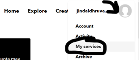
Before we create an applet, we need to get our IFTTT webhook credentials. So basically, Web Hook is a service will allows us to integrate services offered by IFTTT with our Bolt Module. I will explain its working in the next step. For now, let’s get out credentials. To do that, click on the Profile Icon on the top right on click on My Services. Scroll down and click on WebHooks and then click on Documentation in the top right.
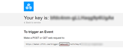
In the documentation you would get a unique webhook link for your account. Make sure that you don’t share it with anyone. In the link, you would see a parameter named event. You can set it to anything but in my case , I’m gonna call it makecall. Now copy the entire link and keep it safe as this is the link which we will call to trigger the webhook and place a call.
2.2 Creating the Applet
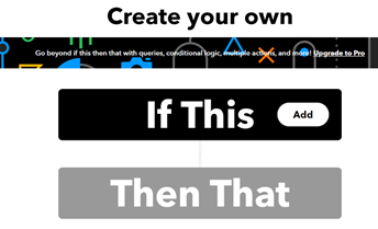
To create an applet, click on Create on the top right of the page. IFTTT works on the principle of IF THIS THEN THAT. It means if this happens then do that. So in our case the thing which is happening is the webhook being triggered with bolt’s pin 0 is high and when it happens, we want to place a VoIP Call.
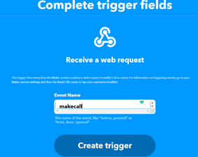
So to do that, click on If This and search and choose Webhooks. Next, there is 1 option and that is Receive a web request and we select it. Now we have to enter the event name which we chose in the previous step. So in my case, it was makecall. Then, click on Create Trigger.
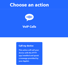
So now we want to select an action which is triggered as soon as the webhook is called. For that, click on Then That and select VoIP Calls. Then select call my device . After that if you get an option to connect your device , please do so by clicking on the connect button.
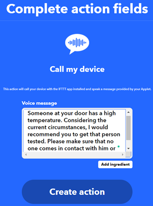
Next, we get an option to set the text which will be said during the call. You can set it to whatever you like. Just to try it out, enter the URL which we got to trigger the webhook in any browser. Within seconds, you would get a phone call on your phone and when you pick it up, you would be able to hear the voice message.
3.CODING THE BOLT MODULE
Now in this section, we will be seeing how the device is able to perform the best and most useful functions of placing the call by calling the IFTTT webhook and sending automated emails using Mailgun.
3.1 Getting all The Credentials
Before we start uploading code onto the Bolt Module , we should collect all the required credentials.
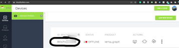
a) BOLT CREDENTIALS: There are 2 credentials which we need to connect to out bolt module and those our the API KEY and the DEVICE ID. To find them, head over to https://cloud.boltiot.com/ and you
would see the device ID in the dashboard. It would be something like BOLTXXXX. Next, on the left panel, you would find an API button. Click on it and then copy your API Key. Copy both of them and save it somewhere.
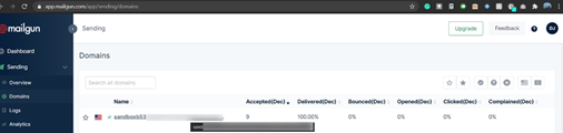
B) MAILGUN CREDENTIALS: We will be using an online service named Mailgun for sending the automated email. Firstly sign up or login by heading over to https://www.mailgun.com/. Then start off by creating a sending domain. Once you have done that, go to Sending>>Do mains and click on your sending domain. Firstly you would see your Sandbox URL which is something like sandboxXXXX.mailgun.org. Your sender email is test@yourSandboxURL.
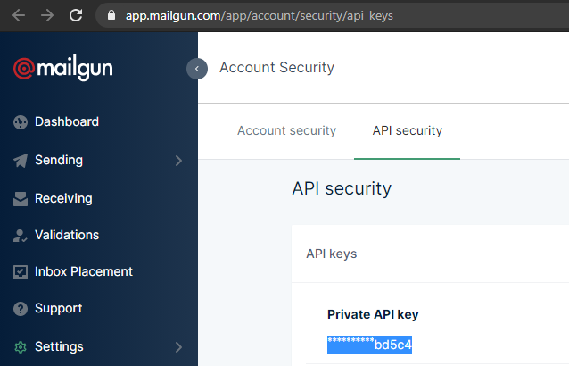
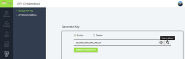
To find your Mailgun API key, click on API Keys on the right. Then you would be redirected to a page where you would be able to see your API key. From there, copy your private API key.
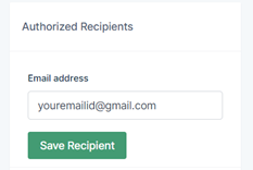
There is just 1 last thing and that is to Add Recipient. Mailgun does not allow sending emails to an email address until and unless you verify it first. To do so, go back to the sender page and on the right hand side, you would get an option to Save Recipient. An email would then have been send by Mailgin to the email address you provided to verify it. Once you do so, your email address would become a verified recipient.
3.2 Creating the conf.py file
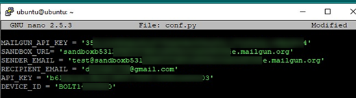
Firstly, open set up a virtual machine and run ubuntu on it. We are creating a file named conf.py and it will store all the credentials we got from the previous step. To create the file, type nano confy.py and hit enter. Inside the file, enter all the credentials in this manner:
Once you have done that, click CTRL + X and then Y to save and exit.
3.2 Creating the high_temp.py file
As before, we will create a new file using nano high_temp.py. Before I show you the code, let me explain to you what we expect from it. Firstly, what we want is that the code gets the status of the pin 0. We know that if the person has a high temperature, the D6 pin of the NodeMCU which is connected with the digital pin 0 of the Bolt module turns high. So if the status is high, we want to send an email using mailgun and also make a web request which places the call via IFTTT. Also, also want to print the response for troubleshooting cases.
Here is the code:
# IMPORTING THE LIBRARIES
import requests ##library which will help in making web request
import conf # the file with all the credentials
from boltiot import Email, Bolt #Bolt Iot libraries
import json, time #Other libraries which  we will need


mybolt = Bolt(conf.API_KEY, conf.DEVICE_ID) # establishing connection with the bolt module
mailer = Email(conf.MAILGUN_API_KEY, conf.SANDBOX_URL, conf.SENDER_EMAIL,conf.RECIPIENT_EMAIL)#creating the mailer object

while True:
    response = mybolt.digitalRead('0')#Pin high when high temperature and pin low when low temperature
    data = json.loads(response #Loading the data
    decision = data['value'].rstrip() # decosion will be 1 for high temperature and 0 for low temperature
    if decision == "1": #if person has high temperature
        print("Arranging Phone Call")
        r= requests.get("http://maker.ifttt.com/trigger/makecall/with/key/lC5kvr7aPRfsnzUe6diZygd7vthmOn0Oa530qvbw-lm") #Calling the webhook
        print("Making request to Mailgun to send an email")
        response = mailer.send_email("Alert!", "Someone whith a high temperature has just entered the building.") # ("Subbect", "Body")
        response_text = json.loads(response.text)#response from mailgun
        print("Response received from Mailgun is: " + str(response_text['message'])) #printing the response for troubleshooting purpouses

    elif decision =="0":
        print("low temperature")
    else:
        print("error")

    time.sleep(4)#code executes again after 4 seconds.
4.SCHEMATICS AND CONNECTIONS
![]() 4.1 – PCB Designing
4.1 – PCB Designing
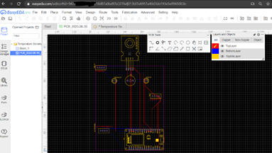
When I was finished with building the initial prototype of this product, it worked properly but it would not have for long due to the ton of connections which could become loose and come out at any moment. That’s why I decided to try my hand in PCB designing.
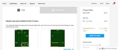
I used an online website named EasyEda to make design the PCB and then gave it order to JLCPCB. Once the PCB had arrived, I soldered most of components onto it and for the rest, I soldered female header bug strips and then attached the components later.
This is a schematic of the PCB:
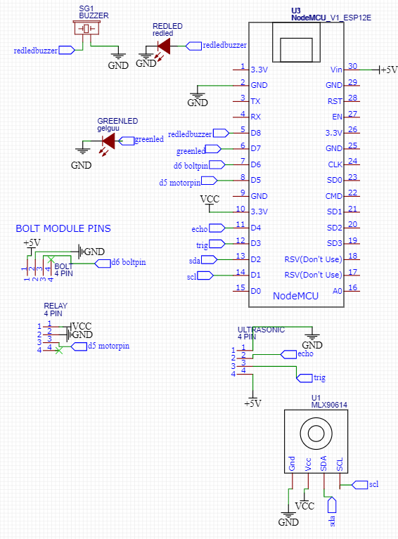
PS: Instead of connecting the pins in the schematics, I have added net ports so that it is neater and easier to understand.
4.2 External Connections:
The above schematic is just of the PCB and of the pins which would be attached to it. There were also a few more connections left for which I am making a diagram below. Please note that the below connections are the external ones, the rest of the connections have been implemented into the PCB.
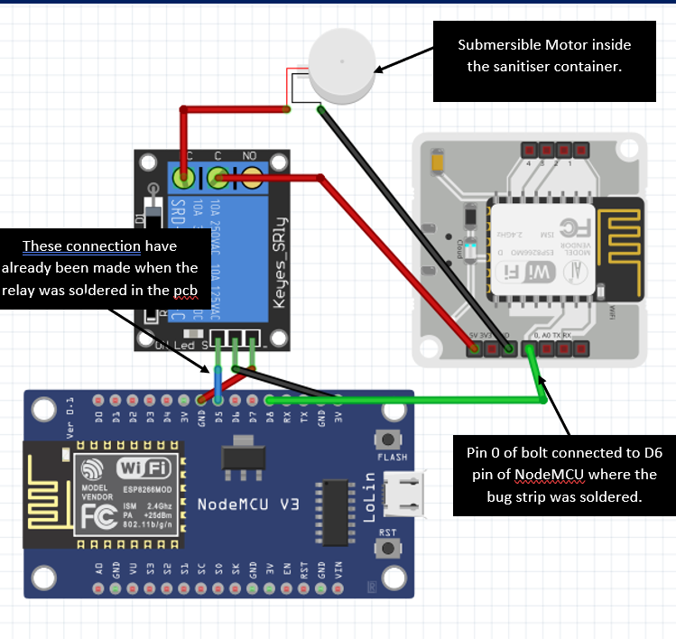
In the above schematic, I have shown the external connections.It is mainly the connection between the bolt module, relay and NodeMCU. The 3 input pins of the relay had been soldered in the PCB. Now when the replay turned high, I wanted the submersible motor inside the sanitiser container to work. So I connected the Ground of the Motor to ground of the Bolt Module. The 5v of the motor was connected to NC of the relay which is stands for normally closed and the 5v of the Bolt Module was connected to the COM port of the relay. In this way, whenever I programmed the relay to become high, the motor turned on.
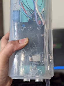
5. HARDWARE
There were a few parts whose placing plays an important role. I just wated to show them to you as well.
MOTOR:
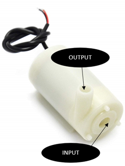
The motor was placed inside of a container filled with sanitiser. As it was submerged completely in sanitiser, it could take the sanitizer through the input hole. And on the output hole, I attached one end of a plastic tube and the other end is attached to the bottom of the enclosure near the ultrasonic sensor. This is how I have placed the motor in the project:
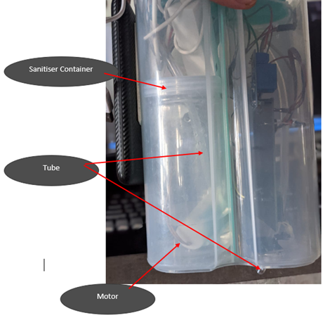
The container contained sanitizer which is alcohol based. This means if the top of the container is not covered, all the sanitizer would evaporate. To prevent that, I put the cap of the container on it and made 2 holes, 1 for the tube and the other for the 2 wires.
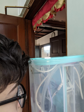
ULTRASONIC SENSOR:
The Ultrasonic sensor has been placed at the bottom of the device and next to the hole made for the plastic tube. So now, when the user places their hand below the device, the ultrasonic sensor detects their hand and the sanitiser is immediately dispensed right there. I used a hand drill to make holes in the bottom and make way for the ultrasonic sensor.
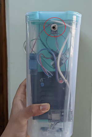
TEMPERATURE SENSOR:
I have placed the temperature sensor at the top of the device so that the user does not have to bend to get his/her temperature scanned. I used a hand drill to make a hole for the sensor.
DEMONSTRATION
Before I start testing, I have uploaded the code on the nodeMCU board with the Arduino IDE, run the python script on my laptop and lastly connected the device with a power bank.
1.Testing the sanitiser dispenser and temperature detection.
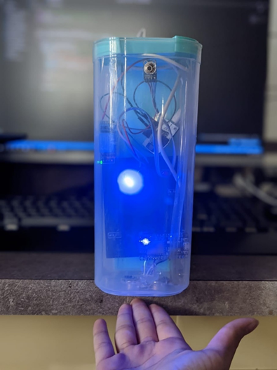
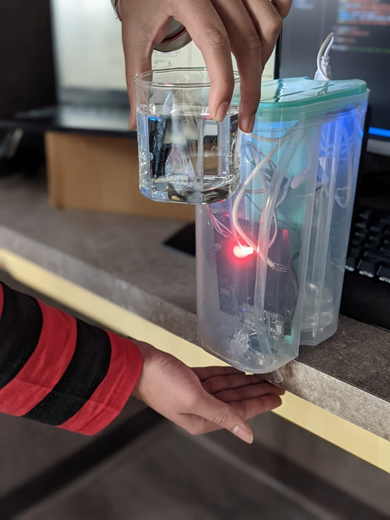
In order to check if the temperature sensor and the sanitiser dispenser were working properly, I used the ambient room temperature in one case and a hot glass of water to stimulate the high temperature. The results were exactly as expected. In the first case, the blue led lit up and the sanitiser was dispensed and in the second case, the buzzer and red led were triggered along with the sanitiser dispensing.
CASE 1:
2.Testing the Mail and Calling Feature.
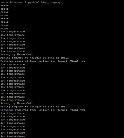
To test if these 2 key features were working , I ran the python script on my laptop. I first checked the terminal as the status was being printed there.
This is how the terminal looked like. It showed error in the starting because the device wasn’t powered on.
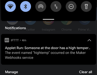
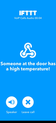
This is the automated notification which was sent on the phone by IFTTT.:
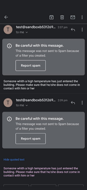
This is the automated mail which was sent:
And lastly, this is the call which was placed.
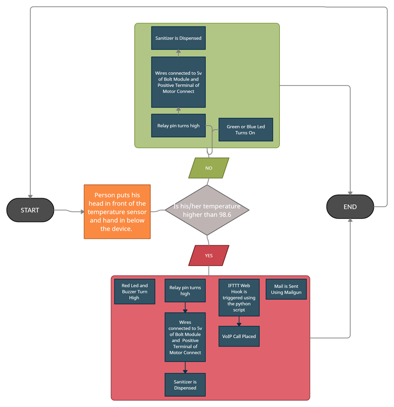
3.Flow Chart
I also wanted to show you the entire flow of the project in case you had any confusions.
4.FullVideo
If you want to see this entire project in action, click HERE .