This project is all about adding Luxury to life using bolt IoT module. In this project I am going to build automatic window curtain that will open up automatically giving you some sunshine every morning .
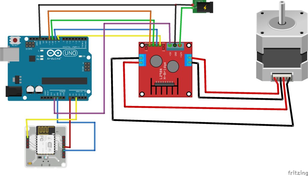
Connect the A+, A-, B+ and B- wires from the stepper motor to the module out1, out2, out3 and out4 respectively.
Here we have provided l298n controller with external 12v and 5v power supply so remove the onboard voltage regulator jumper.
Connect stepper motor driver module to arduino using 4 jumper wires.
Connect wires from IN1,IN2,IN3,IN4 from driver module to pins 8,9,10,11 on arduino respectively.
Connect external 12v to the driver module and 5v from arduino as shown.
circuit digram
Now lets make curtain
Clamp the clamp to a surface leaving the space for the rod in between.
Suspend one end of the rod on clamp and other end of the rod to stepper motor connected to the clamp.
Fix the curtain cloth on the rod (I fixed it using quickfix adhesive).
Caution: Please ask your parents permission to drill window frame for fixing clamp. It is likely that they deny permission for your crazy idea, my case was same so I drilled and fixed the clamp on my bed’s headboard.
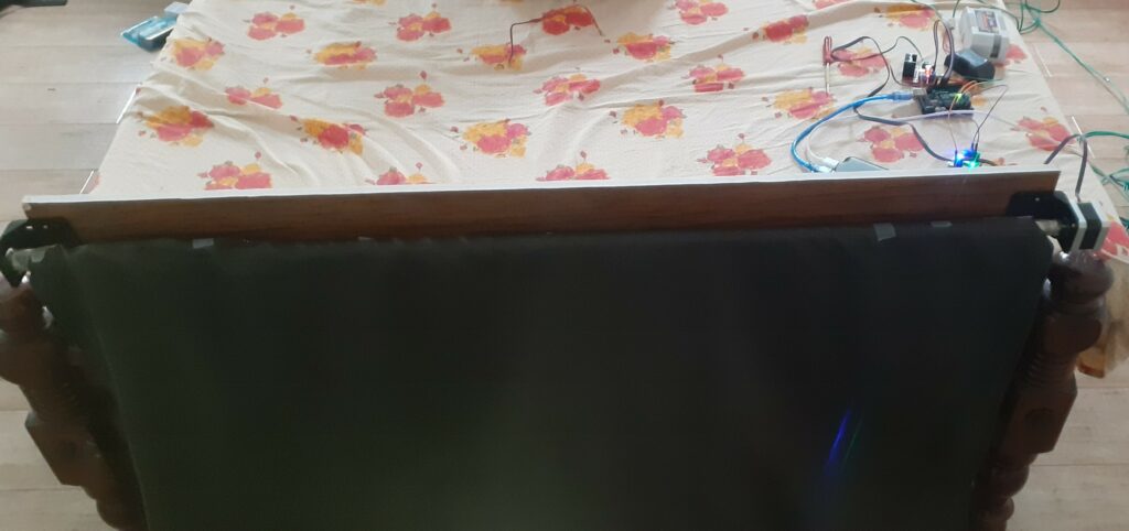
It might look something like this:
Arduino coding
Upload the code below to arduino
#include <Stepper.h>
// Created by Aashik Pradeep on 20/1/2021

int sensorPin = A0;    // select the input pin for the potentiometer
int sensorP = A2;
int sensorValue = 0;
int sensorLValue=0;
const int stepsPerRevolution = 200;  // change this to fit the number of steps per revolution
Stepper myStepper(stepsPerRevolution, 8, 9, 10, 11);

void setup() {

  // set the speed at 60 rpm:
  myStepper.setSpeed(85);
  // initialize the serial port:
  Serial.begin(9600);
}

void loop() {
  sensorValue = analogRead(sensorPin);
     sensorLValue = analogRead(sensorP);


   if(sensorValue>50&&sensorLValue<5){
  Serial.println("clockwise");
  myStepper.step(200); }

  if( sensorLValue>50&&sensorValue<5){
  // step one revolution in the other direction:
  Serial.println("counterclockwise");
  myStepper.step(-200);
  }
 }
Here I have used analog pins instead of digital pins to avoid pullup resistors and its sensitivity issues.
When the Bolt module’s digital pin gives output the analog pin in arduino will read a value between 50 and 5.
When the pin gets input the stepper takes 200 steps clockwise or anticlockwise accordingly.
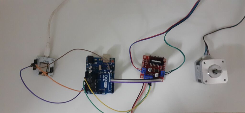
Connecting Bolt to Arduino
Connect A0 AND A2 pins to digital pins 1 and 2 of Bolt module respectively also short the ground of Bolt and Arduino as shown in circuit diagram above.
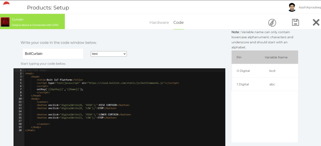
Software coding on Bolt
Create a product on bolt cloud initializing two digital pins of Bolt module.
Here I have used digital pin 0 and digital pin 1, connect them using jumper wires. I have used html language to write the code so that it is simple and all can understand, but if you are a pro go for JavaScript interesting button layouts are readily available in Docs section in Bolt cloud ( https://docs.boltiot.com/docs/controlling-devices ).
By now its all set to run, now use 5v power source (power bank) to power Bolt module and Arduino and stepper motor drive.
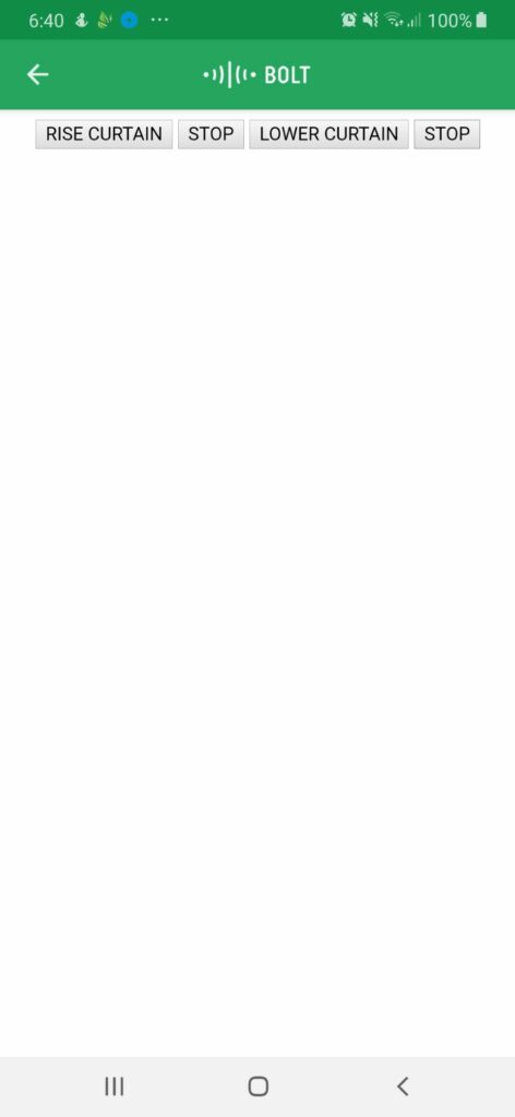
Switch on the 12v power supply to the stepper motor drive. Open bolt app on phone and you will find “RISE CURTAIN” button to rise the curtain & “LOWER CURTAIN”to lower the curtain and stop button to stop rising or lowering of the curtain at desired position.
The good news is seeing this mom allowed me to fix it on window. If you are doing so please make sure there is a power supply near window so u can power 12v external power source for stepper motor.
Making automatic curtain smart
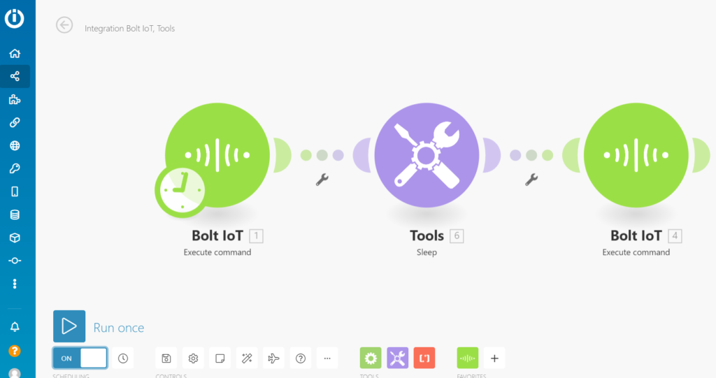
Using integromat you can make your curtain smarter. This will enable the curtain to operate at particular time in a day without your interference.
Here I have used integromat to open the curtain automatically at 6:00am every day and shut it at 7:00pm every day.
Steps for linking integromat
Create account on integromat
Create New Scenario using Button which is located on the Top Right Corner of your page.
Type Bolt IOT in the Search Box or You can Scroll Down and find the Bolt IOT Icon.
Click on? Icon and Click on Bolt IOT. The Module will ask for Connection and Command. Click on Add Connection, it will ask for API key and Connection Name.
Type in device name and api key which are available on your bolt cloud.
Now Select the Command Box. It Drops down into a List. In the GPIO List, Select Write Digital Output.
The Name of the Device must be Entered in the Device name Box. In the Pin Box Type 0 and in the State Box Type “High”. Then Select Continue.
Then Select Tools Icon.
Select Sleep Option and Link it with the Bolt Module. Set Delay as per time required for your curtain to rise up completely.
Then Add Another Bolt Module next to the Tools Icon, Select the Same Connection and Same Command as mentioned above.
Once Again type the Device Name, Pin No. (0) and in the state Box, Type “LOW”.
Now click on a clock icon on first bolt module, then set the required time which is the time of the day you want your curtain to rise, and if you want it to happen every day select everyday on run scenario.
Now you have automated rising of curtain ,for automating lowering of curtain do the same steps except of pin 0 use pin 1.
Getting up in the morning with sunshine already in your room is likely to make you happy and energetic. Also enjoy the ease of lowering and rising the curtain at your comfort place without getting up. Hope this Bolt Iot project brings some sunshine to you and your room.
This project is very use full for all Garden lovers they can easily irrigate watering the plants by using Automatic Garden Irrigation System.
Things used in this project
Hardware Components
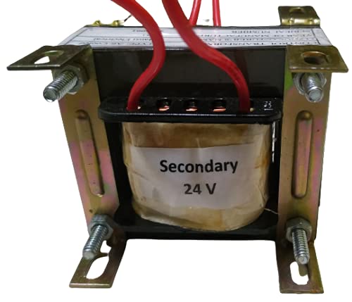
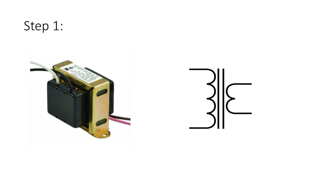
24v Step Down Transformer
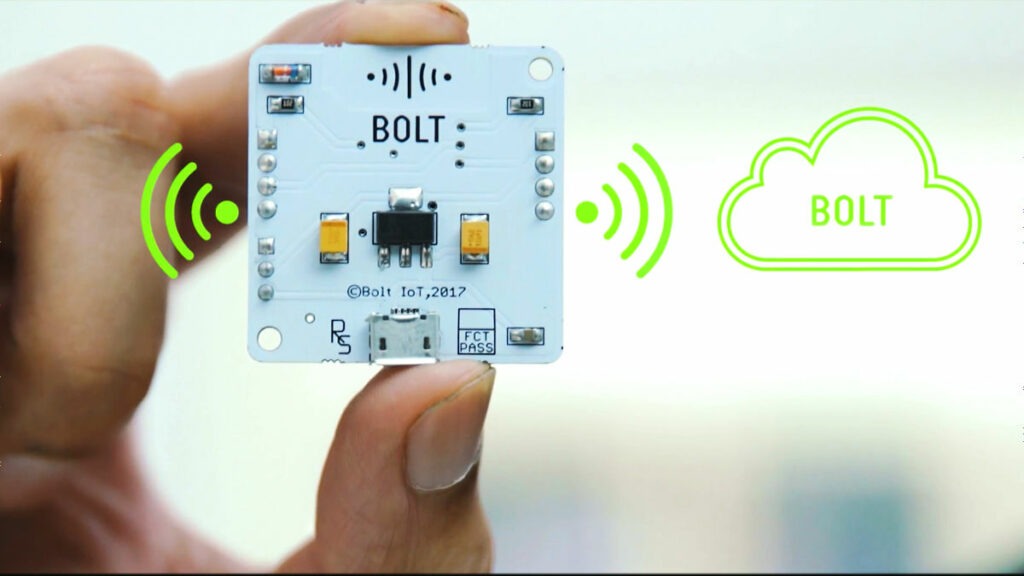
Bolt Wifi Module with Course access
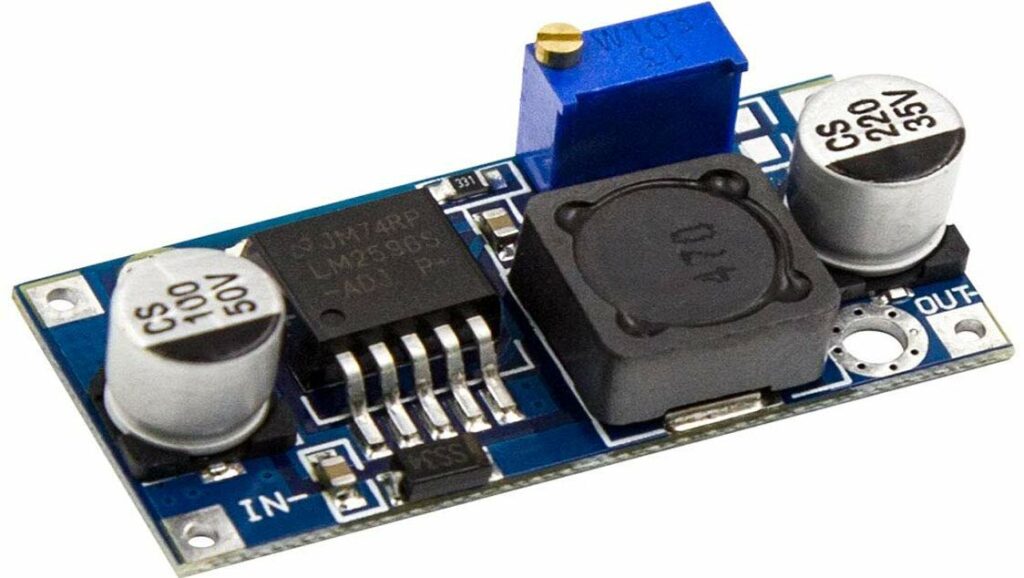
12v DC-DC Buck Converter (1)
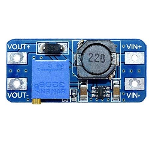
5v-12v Boost Converter (2)
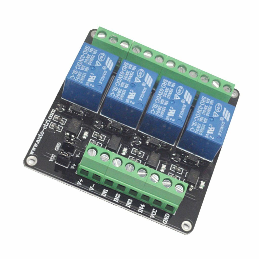
3 Channel 3v relay module
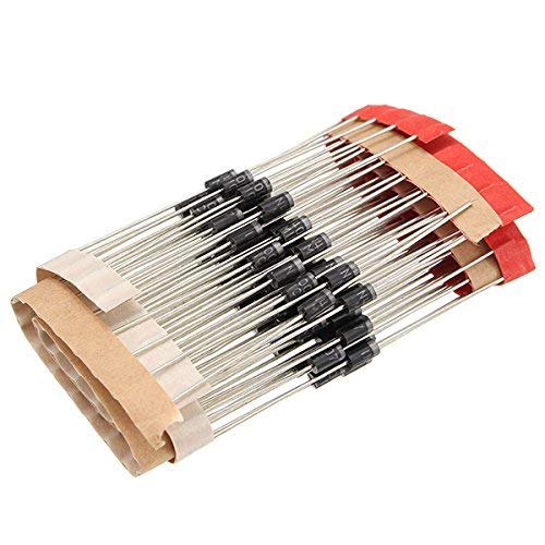
INR007 Diodes (4)
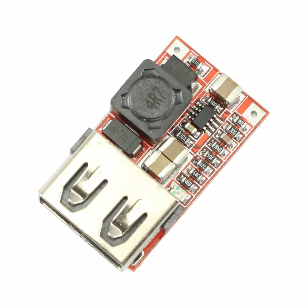
5v Buck Converter with USB
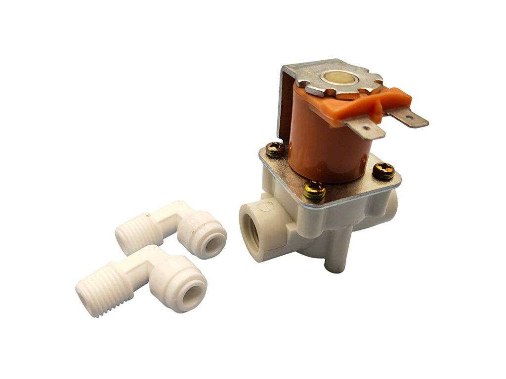
12v DC Solenoid Gate Valves (2)
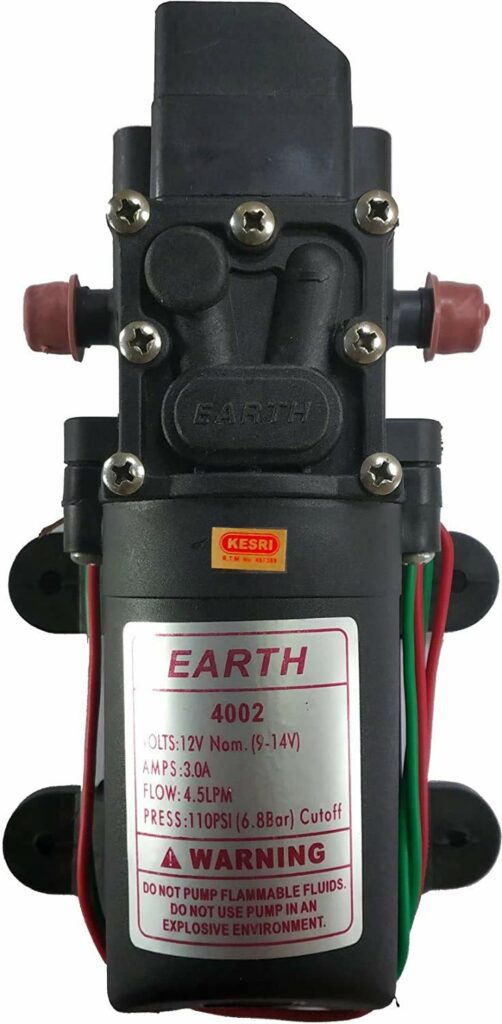
12v DC water Pump
Software, Apps and Online Services
Bolt Cloud Service
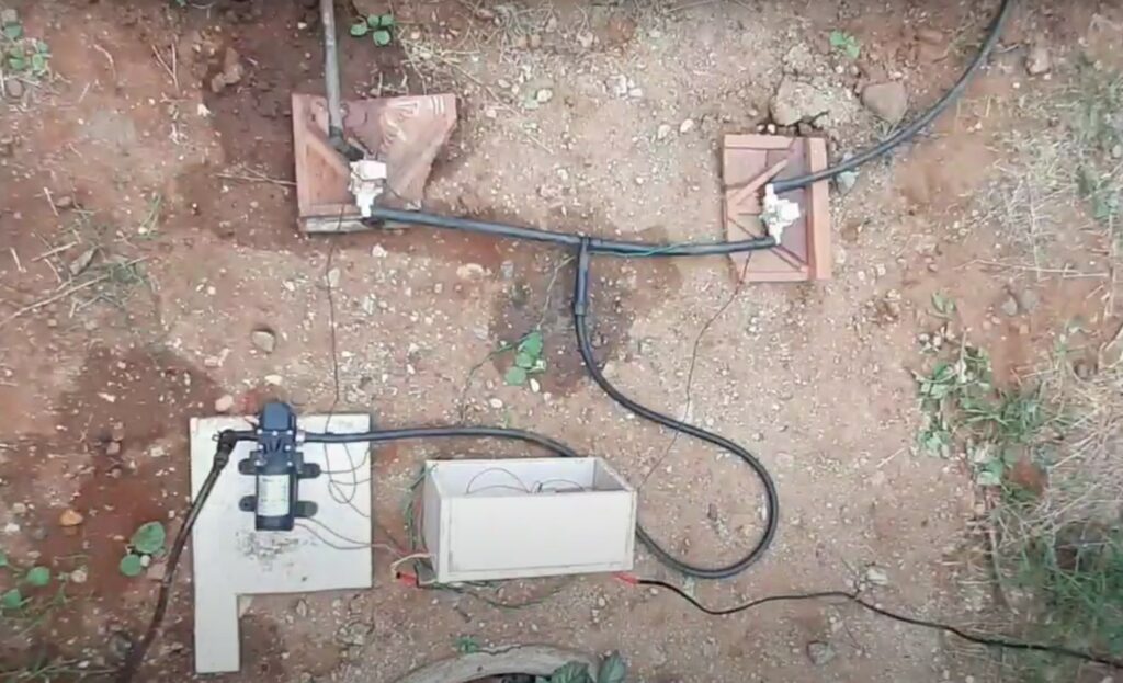
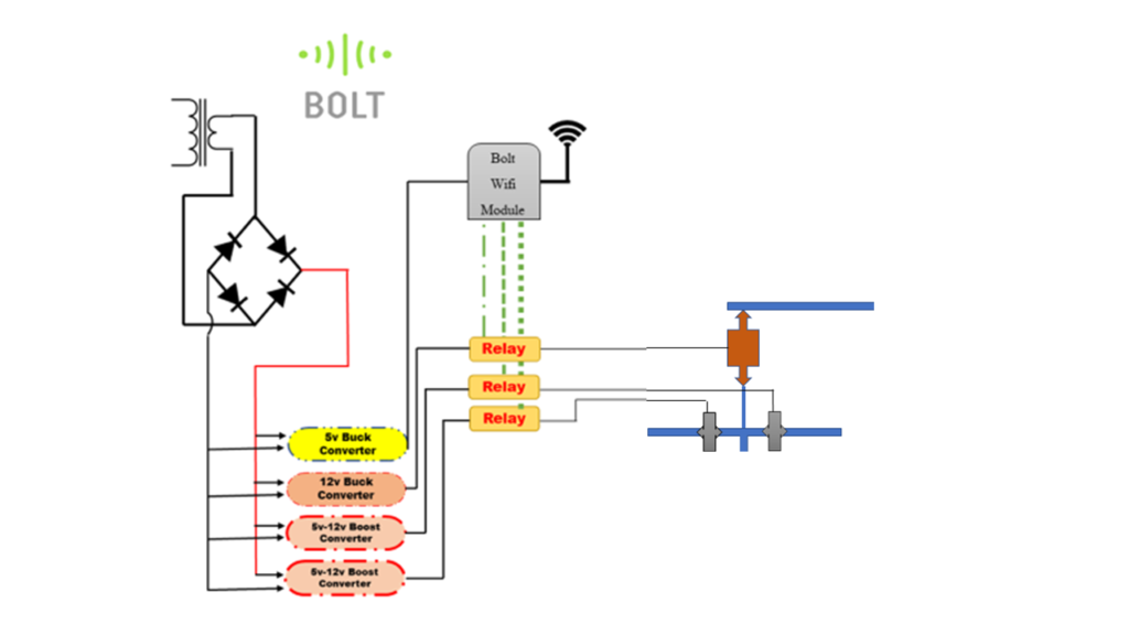
Hardware Setup
1). Fix a transformer in a correct place, shown in figure(1.1).
figure(1.1)
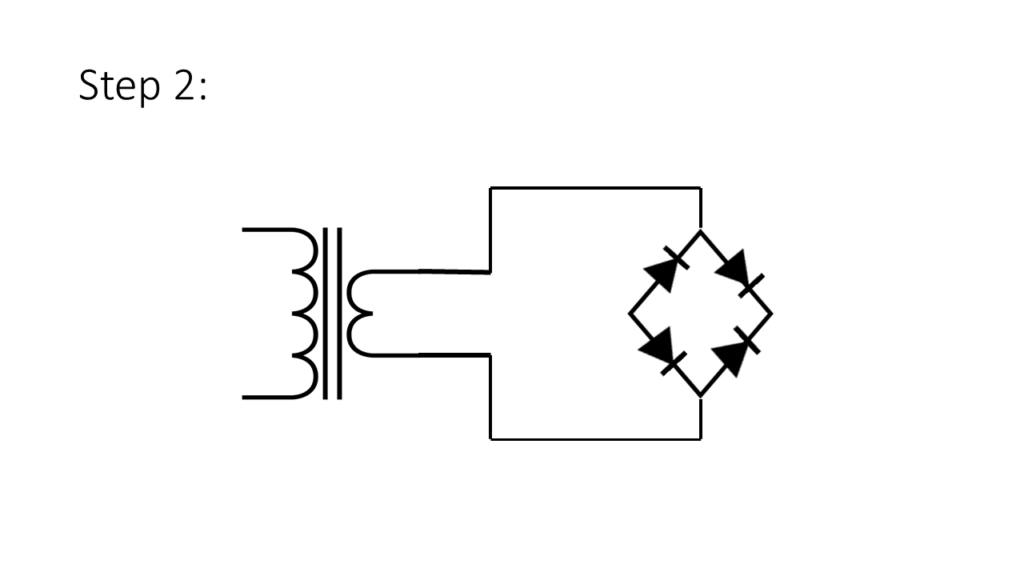
2).Connect a transformer’s secondary winding into a full wave rectifier, shown in figure(1.2).
figure(1.2)
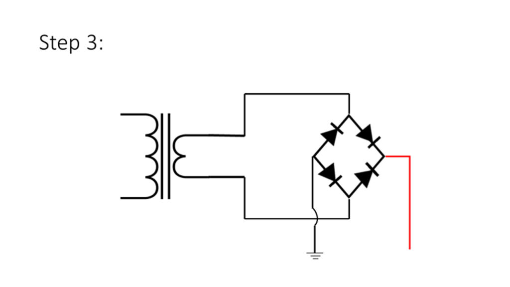
3).Take a two terminals(+,-) out from full wave rectifier, shown in figure(1.3).
figure(1.3)
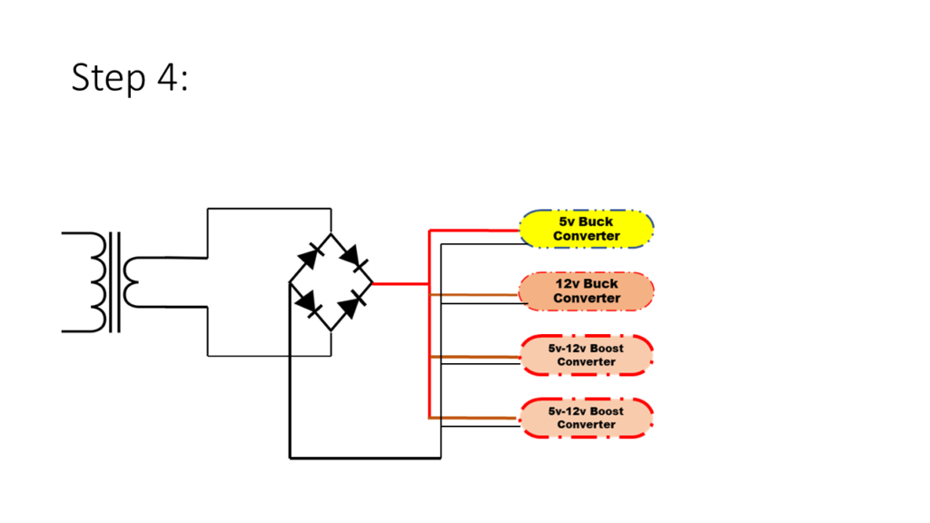
4).place a 5v Buck Converter, 12v Buck Converter & 5v-12v Boost Converter(2) one by one, shown in figure(1.4).
figure(1.4)
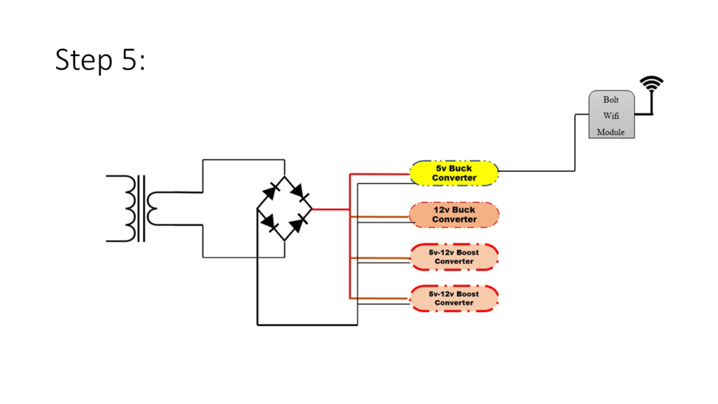
5).Connect a output of the 5v Buck Converter to BOLT wifi module for power supply, shown in figure(1.5).
figure(1.5)
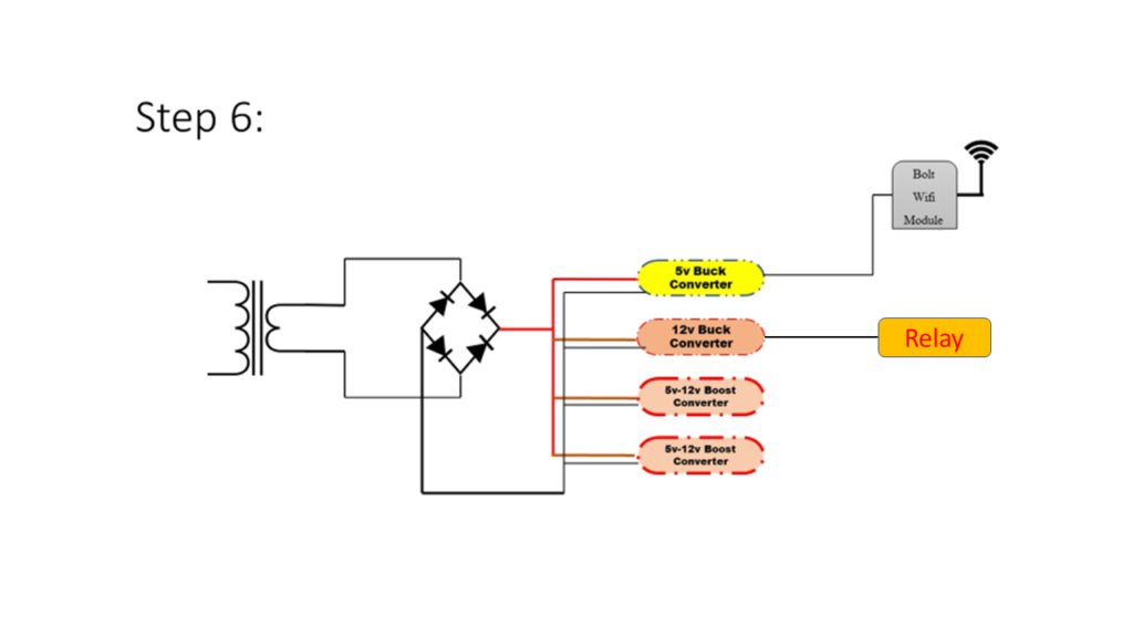
6).Connect a output of the 12v Buck Converter into a 3v relay module as a input supply for relay, shown in figure(1.6).
figure(1.6)
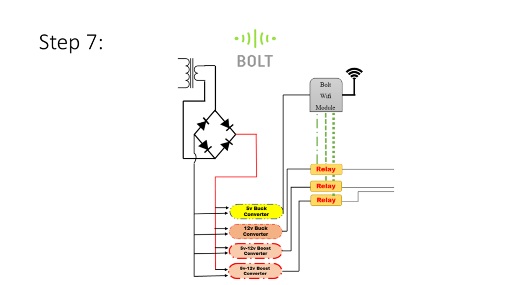
7).Connect a output of the 5v-12v boost converter into a 3v-relay module input supply terminal. At the same time you also connect the jumper wires in the relay output terminal, shown in figure(1.7).
figure(1.7)
8).Connect a port 1 of the wifi module to 1st relay module. Which it was set for a DC pump electric supply and also connect a port 2&3 to two solenoid gate valves power supply, shown in figure(1.8).
figure(1.8)
NOTE: It is your wish you can fix a more gate valves for irrigating a more plants in gardening . hence, the gate valve is used for dividing into small chunks for irrigation because we have only used the 12v dc pump it has a small pressure to pump out the water . So we want to irrigate a big garden we have to install gate valves to irrigate a plants for a long distance.
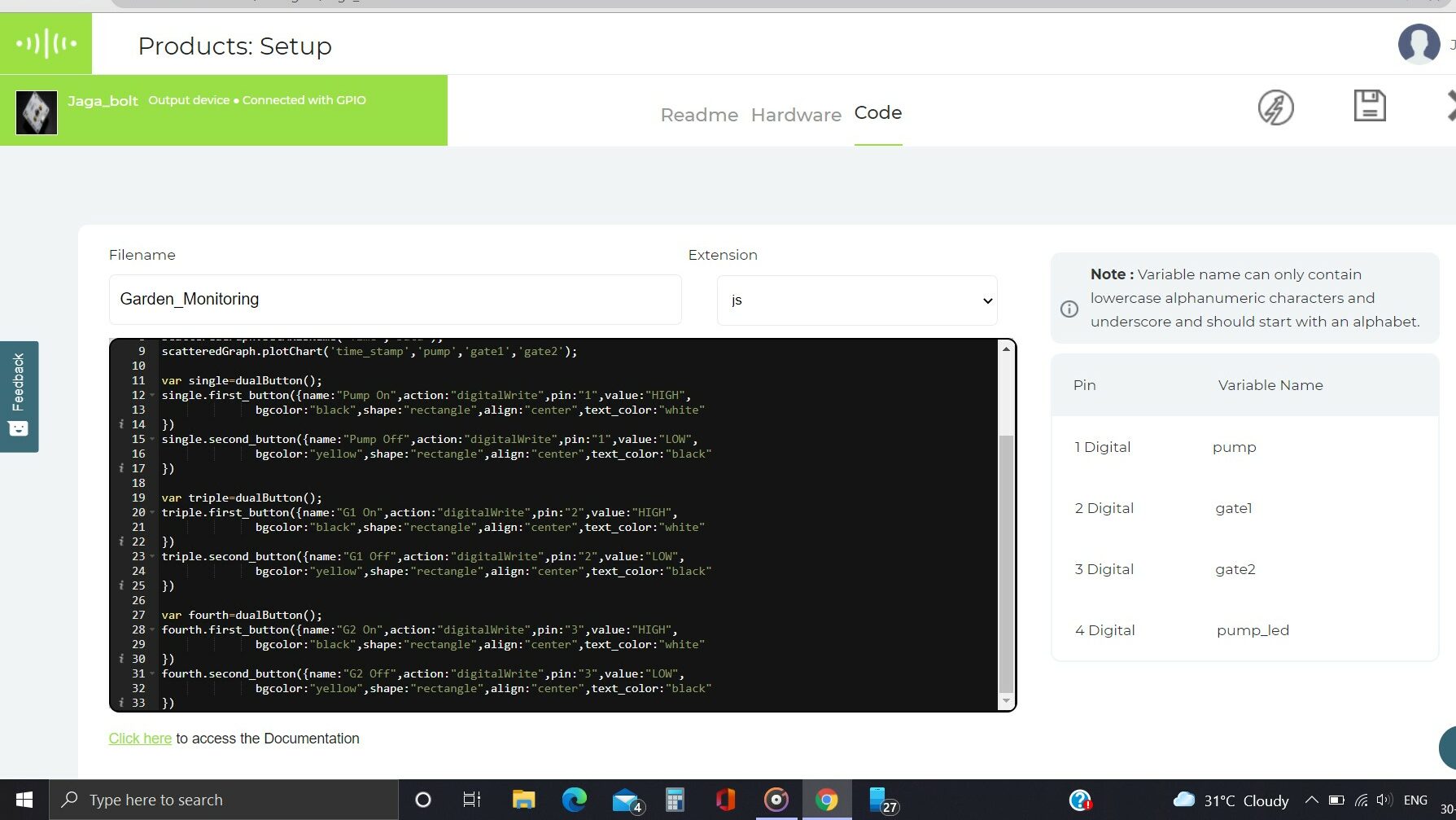
Software Programming
we just want to create a button setup in bolt cloud product setup section easily.
var histogramGraph=new boltGraph();
histogramGraph.setChartType('steppedGraph');
histogramGraph.setAxisName('Time','Data');
histogramGraph.plotChart('time_stamp','pump','gate1','gate2');

var scatteredGraph=new boltGraph();
scatteredGraph.setChartType('scatterGraph');
scatteredGraph.setAxisName('Time','Data');
scatteredGraph.plotChart('time_stamp','pump','gate1','gate2');

var single=dualButton();
single.first_button({name:"Pump On",action:"digitalWrite",pin:"1",value:"HIGH",
 bgcolor:"black",shape:"rectangle",align:"center",text_color:"white"
})
single.second_button({name:"Pump Off",action:"digitalWrite",pin:"1",value:"LOW",
              bgcolor:"yellow",shape:"rectangle",align:"center",text_color:"black"
})

var double=dualButton();
double.first_button({name:"G1 On",action:"digitalWrite",pin:"2",value:"HIGH",
              bgcolor:"black",shape:"rectangle",align:"center",text_color:"white"
})
double.second_button({name:"G1 Off",action:"digitalWrite",pin:"2",value:"LOW",
              bgcolor:"yellow",shape:"rectangle",align:"center",text_color:"black"
})

var triple=dualButton();
triple.first_button({name:"G2 On",action:"digitalWrite",pin:"3",value:"HIGH",
              bgcolor:"black",shape:"rectangle",align:"center",text_color:"white"
})
triple.second_button({name:"G2 Off",action:"digitalWrite",pin:"3",value:"LOW",
              bgcolor:"yellow",shape:"rectangle",align:"center",text_color:"black"
})
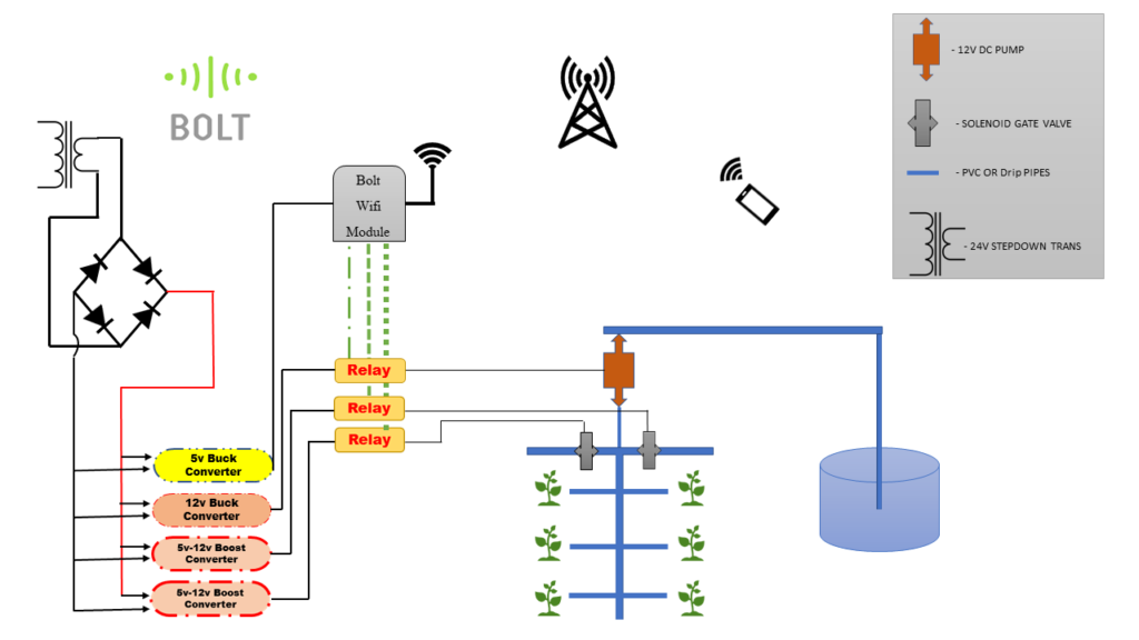
Schematic Diagram
Automatic Garden Irrigation using Bolt wifi Module.
Conclusion
We will irrigate a garden in everywhere through the internet by using Bolt wifi module & cloud service.
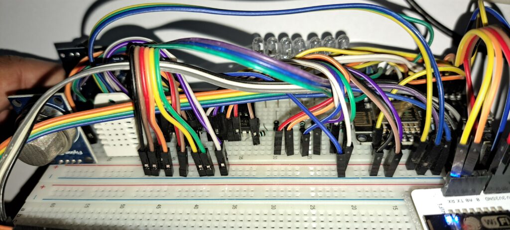
Step 1) Connect the DHT-22 Temperature and Humidity Sensor with the NodeMCU ESP8266 and Bolt IoT Module as per the following:
Vcc (DHT-22) is connected to 3.3 V (Bolt IoT Module)
Gnd (DHT-22) is connected to Gnd (Bolt IoT Module)
Data (DHT-22) is connected to D5 (NodeMCU ESP8266)
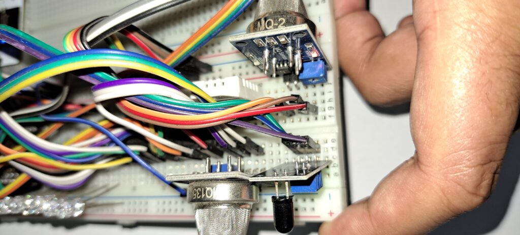
Step 2) Connect the MQ-135 Air Quality Sensor with the NodeMCU ESP8266 and Bolt IoT Module as per the following:
Vcc (MQ-135) is connected to 3.3 V (Bolt IoT Module)
Gnd (MQ-135) is connected to Gnd (Bolt IoT Module)
A0 (MQ-135) is connected to Channel 1 (CD4051 IC)
Step 3) Connect the MQ-2 LPG, Carbon Monoxide and Smoke Sensor with the NodeMCU ESP8266 and Bolt IoT Module as per the following:
Vcc (MQ-2) is connected to 3.3 V (Bolt IoT Module)
Gnd (MQ-2) is connected to Gnd (Bolt IoT Module)
A0 (MQ-2) is connected to Channel 0 (CD4051 IC)
Step 4) Connect the Fire Sensor with the NodeMCU ESP8266 and Bolt IoT Module as per the following:
Vcc (Fire sensor) is connected to 3.3 V (Bolt IoT Module)
Gnd (Fire sensor) is connected to Gnd (Bolt IoT Module)
D0 (Fire sensor) is connected to D0 (NodeMCU ESP8266)
Step 5) Connect each 7 LEDs to 150 Ohm Resistor which are then connected QA, QB, QC, QD, QE, QF, QG of SN74HC595 IC.
Step 6) Connect the 20×4 LCD with I2C module with the NodeMCU ESP8266 and Bolt IoT Module as per the following:
Vcc (I2C Module) is connected to 5 V (Bolt IoT Module)
Gnd (I2C Module) is connected to Gnd (Bolt IoT Module)
SCL (I2C Module) is connected to D1 (NodeMCU ESP8266)
SDA (I2C Module) is connected to D2 (NodeMCU ESP8266)
Step 7) Connect the SN74HC595 IC with the NodeMCU ESP8266 and Bolt IoT Module as per the following:
Vcc (SN74HC595 IC) is connected to 3.3 V (Bolt IoT Module)
SRCLR’ (SN74HC595 IC) is connected to 3.3 V (Bolt IoT Module)
Gnd (SN74HC595 IC) is connected to Gnd (Bolt IoT Module)
OE’ (SN74HC595 IC) is connected to Gnd (Bolt IoT Module)
SER (SN74HC595 IC) is connected to D6 (NodeMCU ESP8266)
RCLK (SN74HC595 IC) is connected to D7 (NodeMCU ESP8266)
SRCLK (SN74HC595 IC) is connected to D8 (NodeMCU ESP8266)
Step 8) Connect the Buzzer with the NodeMCU ESP8266 and Bolt IoT Module as per the following:
Vcc (Buzzer) is connected to 3.3 V (Bolt IoT Module)
Gnd (Buzzer) is connected to Gnd (Bolt IoT Module)
I/O (Buzzer) is connected to D3 (NodeMCU ESP8266)
Step 9) Connect the CD4051 IC with the NodeMCU ESP8266 and Bolt IoT Module as per the following:
Vdd (CD4051 IC) is connected to 3.3 V (Bolt IoT Module)
Gnd, Input B, Input C, Inhibit, Vss, Vee (CD4051 IC) is connected to Gnd (Bolt IoT Module)
Common in/out (CD4051 IC) is connected to A0 (NodeMCU ESP8266)
Input A (CD4051 IC) is connected to D4 (NodeMCU ESP8266)
Step 10) Bolt IoT Module with NodeMCU ESP8266 as per the following:
5V (Bolt IoT Module) is connected to 5 V (LCD I2C Module)
3.3V(Bolt IoT Module) is connected to 3.3V (NodeMCU ESP8266)
Gnd (Bolt IoT Module) is connected to Gnd(NodeMCU ESP8266)
RX (Bolt IoT Module) is connected to TX (NodeMCU ESP8266)
TX (Bolt IoT Module) is connected to RX(NodeMCU ESP8266)
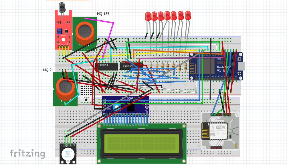
Circuit Diagram
Software Programming
Step 1: Installing ESP8266 Board in Arduino IDE (Windows, Mac OS X, Linux)
The ESP8266 community created an add-on for the Arduino IDE that allows you to program the ESP8266 using the Arduino IDE and its programming language.
Make sure that the latest version of the Arduino IDE installed in your computer. Or install the latest Arduino IDE software from www.arduino.cc/en/Main/Software
Install ESP8266 Add-on in Arduino IDE
To install the ESP8266 board in Arduino IDE, follow these next instructions:
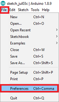
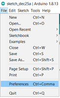
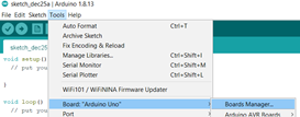
Step 1) In your Arduino IDE, go to File> Preferences
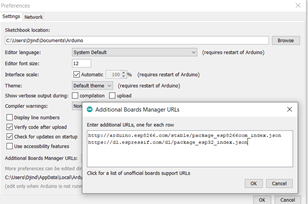
Step 2) Enter http://arduino.esp8266.com/stable/package_esp8266com_index.json into the “Additional Boards Manager URLs” field as shown in the figure below. Then, click the “OK” button.
Note: if you already have the ESP32 boards URL, you can separate the URLs with a comma as follows: https://dl.espressif.com/dl/package_esp32_index.json, http://arduino.esp8266.com/stable/package_esp8266com_index.json
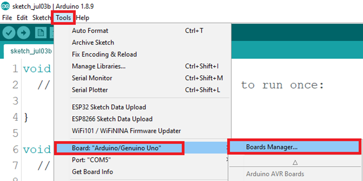
Step 3) Open the Boards Manager. Go to Tools > Board > Boards Manager…
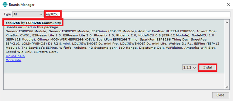
Step 4) Search for ESP8266 and press install button for the “ESP8266 by ESP8266 Community” :
Step 5) That’s it. It should be installed after a few seconds.
Uploading the Sketch to the ESP-12E
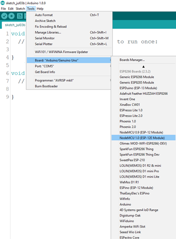
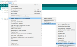
If you’re using an ESP-12E NodeMCU Kit, uploading the sketch is very simple, since it has built-in programmer. Plug your board to your computer. Make sure you have the right board selected:
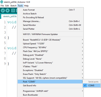
You also need to select the Port:
Before uploading the code, add the following libraries:
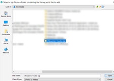
Get the code from the Github Repository of this project. Download a.zip file.
Step 2: Creating a Telegram Bot:
Search for the BotFather in the search menu.
After opening the BotFather enter the command /start to create the bot.
To create a new bot, enter the command /newbot and give a suitable name to the bot.
Secondly, we need to give the username to the bot created it should be ending with the bot e.g. usernamebot
Now an API Key will get generated store that API Key as it has to be used in the coding.
Step 3 Create a new product on the Bolt Cloud.
Create an Account on the Bolt Cloud and linked the Bolt WiFi module to the Cloud account.
Ensure to select the ‘Input Devices’ and ‘UART’ option.
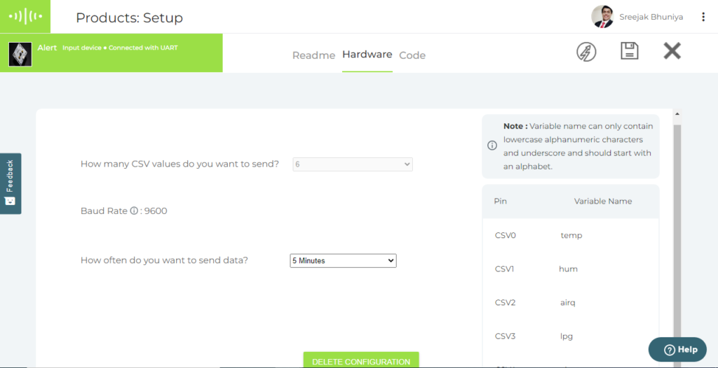
2. Configure the product:
3. Remember to name the code, and set it as “.js” file. Get the code from the Github Repository of this project. Once done save and exit the product configuration view.
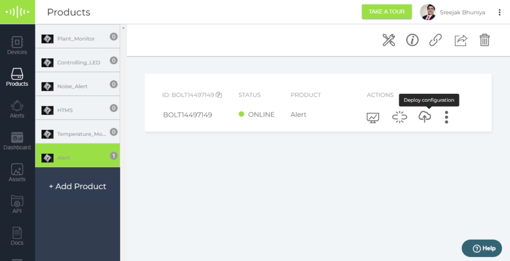
4. Link the Bolt device to your new product. Once the device is linked, remember to click on the Deploy Configurations button.
5. View your device: The Cloud polls the device for data every 5 minutes. I had Bolt IoT Cloud Pro. So, cloud polled the device for data every 30 seconds.
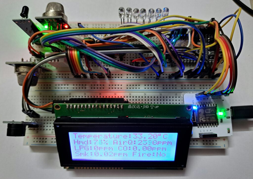
After doing all of the steps, you will have a system that monitor the Temperature, Humidity, Air Quality, LPG, Carbon Monoxide, Smoke and detect Fire in the surrounding environment. It can send alert to Telegram based on the limit set in the telegram app using telegram bot. Telegram app can also be used to monitor the values and download the CSV File from the Bolt IoT Cloud using the date and time entered by the user. The data can be monitored and visualized on the Bolt IoT Cloud Platform. Web Server can also be used to monitor and change the threshold values of the parameters.
In this world where technology is taking over the mankind and we are getting smart and easy solutions for each of our daily faced problems, starting from the electric brush ending with voice controlled room lights. Then why not to make something COOL and CHEAP to help us deal with opening and closing our house door more securely and conveniently. Excited? Lets get into it….
Story/Problem
The main problem that I am trying to solve is to make a cheap and secure way to open our house door by just tapping in our smart phone that can run 24*7.
Things used in this project
Hardware components:-
Bolt-IoT
Arduino pro mini
Servo
5V Adapter
Nylon thread
Software, Apps and online services:-
Bolt-Cloud
IBM-Cloud
Node-Red
Google-Sheet
Mit-APP- Inventor
Arduino IDE
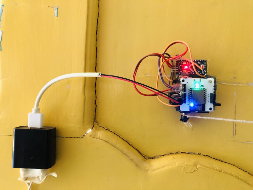
Hardware setup
While making this project I had tried to keep the hardware as simple and as cheap as possible so that the parts if gets damaged can easily be replaced without any hassle.
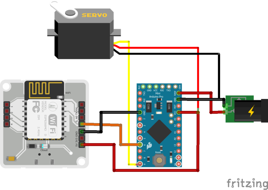
The Schematic diagram is as follow:-
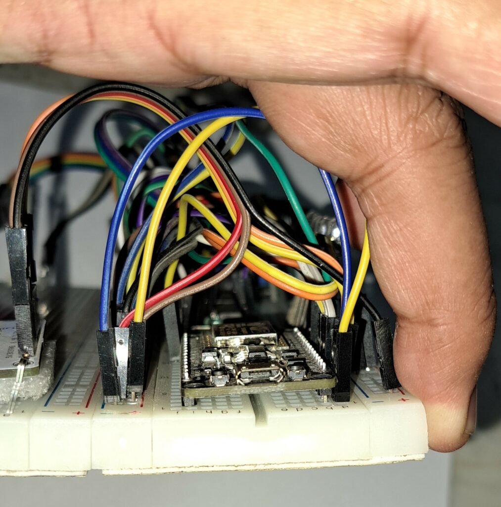
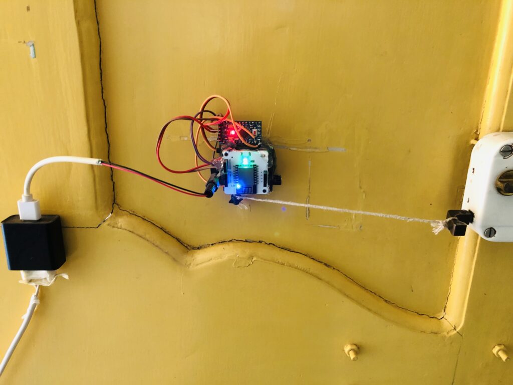
Just do this easy connection with the bolt module and fix this beside the door lock just as the image shown along with the adapter and we are good to go with the software part. We can make the system look more good and compact by hot-gluing the parts together and cutting the extra wires.
Hardware-Setup
Software Programming & Cloud Setup
IBM CLOUD
Setting up the IBM Cloud to host Node-Red so that the backend and logical operation can be done over the cloud without any interruption.
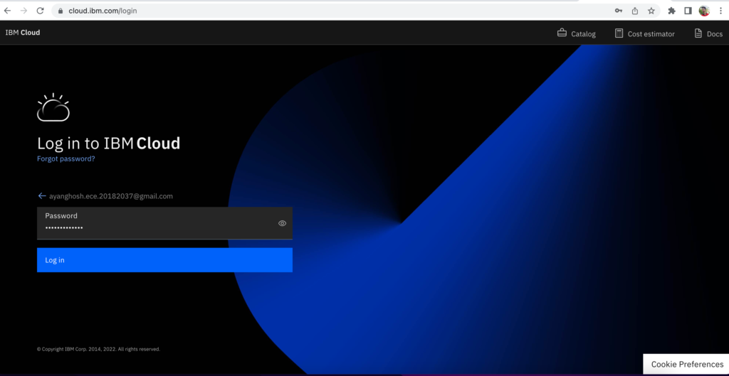
Step 1:- First create an IBM Cloud account from cloud.ibm.com
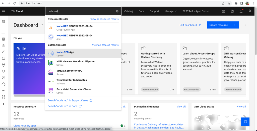
Step 2:- Search for NODE-RED in the search bar. Then select the NODE-RED App.
Step 3:- Follow the steps necessary to deploy the service as mentioned.
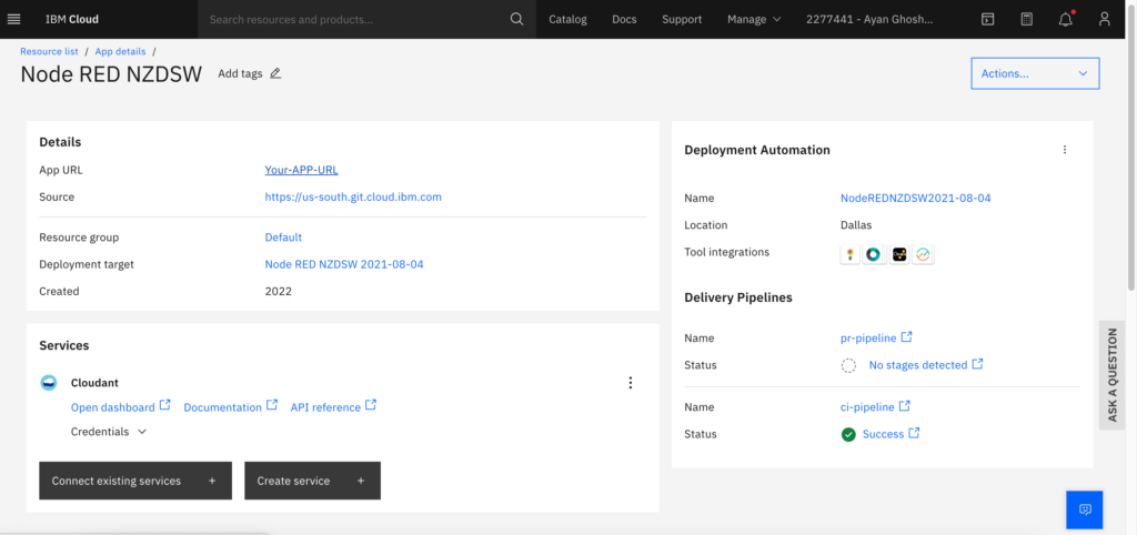
Step 4:- This screen will open after the service is successfully installed. Then click on “Your app link”.
Step 5:- This screen of Node-Red will appear, then click on the “Go to your Node-Red flow editor”
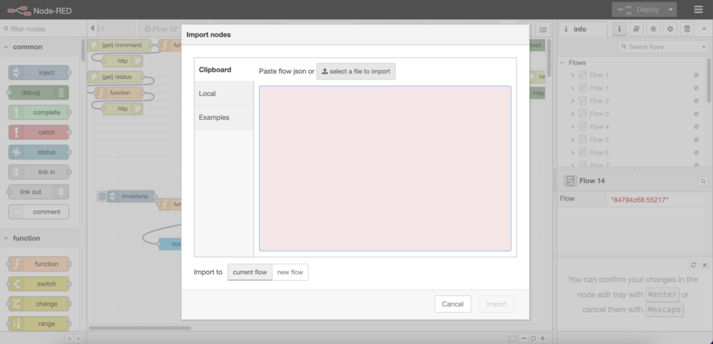
Step 6:- This Node-Red Flow editor will appear then click on the IMPORT and select the noderedflow.json from the Github repo.
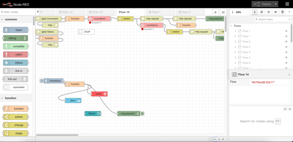
Step 7:- Your flow will look like this, then click on DEPLOY in the upper right corner of the editor.
Step 8:- Copy the link of this node-red flow (This will trigger the system) to put in the MIT-APP-INVENTOR.
NOTE:- Change the BOLT API request URL and also the user phone number.
Bolt-Cloud
Setting up the Bolt Cloud so that it can receive the user input through IBM Cloud and operate the Servo/Actuator to open the door using Arduino.
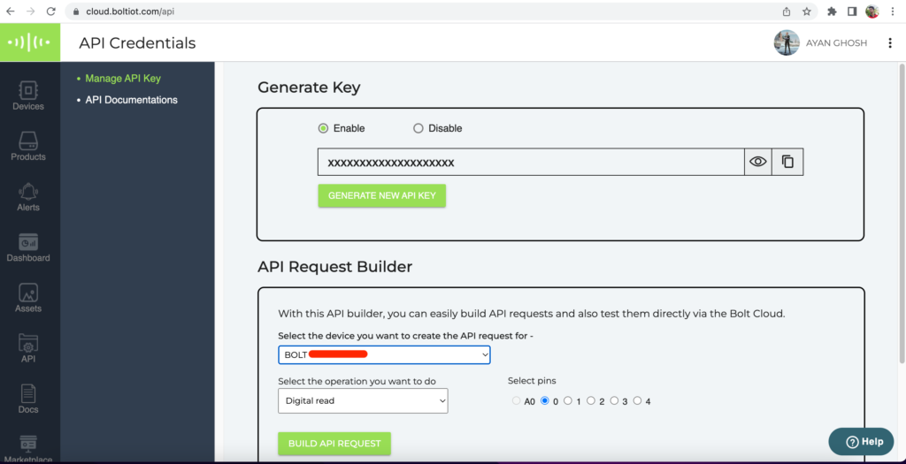
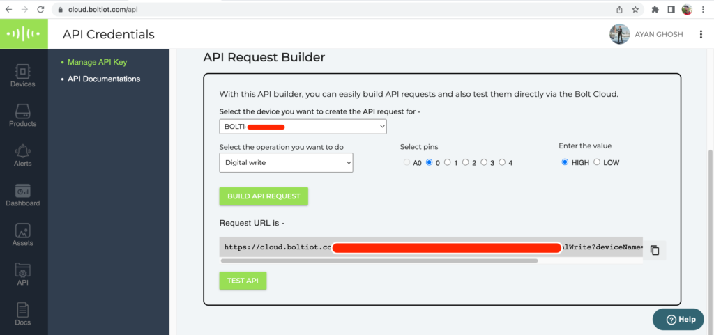
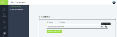
Step 1:- Add your Bolt-Module in the cloud.boltiot.com. After that Enable the API Key in the API section.
Step 2:- Select the right port and device and then click on the “build api request” and add the urls to the Node-red Flow editor.
Step 3:- If by any chance we hit the maximum API request threshold then we can follow the below steps.
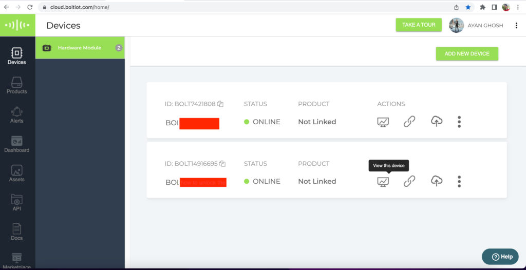
Step 4:- Click on the device section, then beside the correct device choose the “View this device” option.
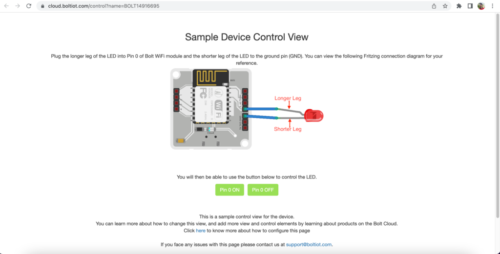
Step 5:- This pre made page will appear integrated with the API request of the DIGITAL PIN 0. We can manually operate the lock by clicking the buttons.
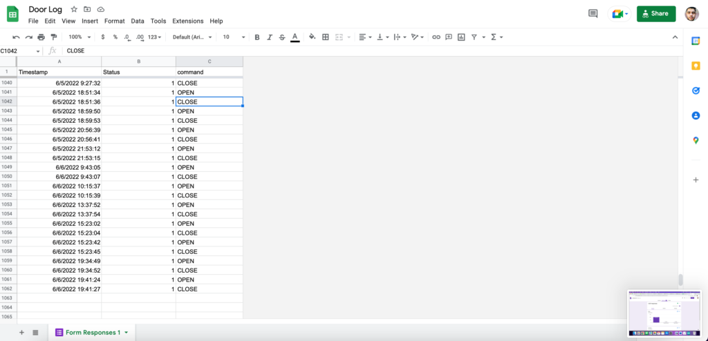
Google Sheet
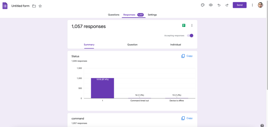
Step 1:- First Create a google form and copy the pre-filled link of the two parameters.
Step 2:- Paste the link in the Node-Red Flow editor in the “google sheet link”.
This type of entry will be stored inside the google sheet after triggering the system to open the door.
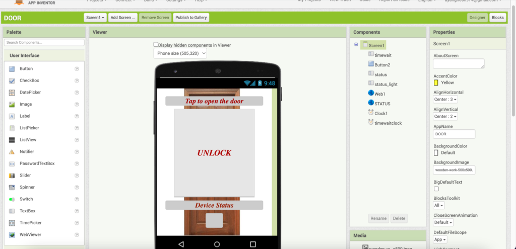
MIT APP INVENTOR
Step 1:- Go to appinventor.mit.edu then click on the create app option in upper left position. Then create/login with your account.
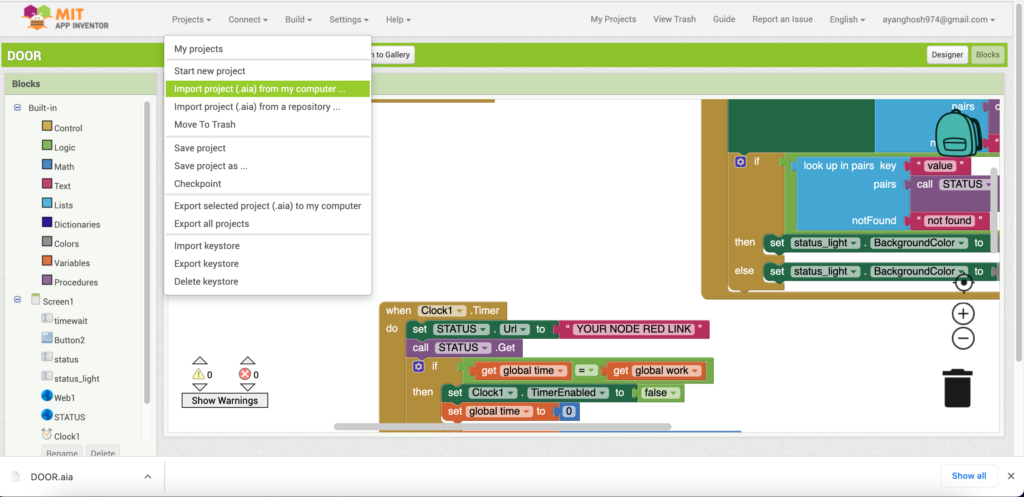
Step 2:- This type of interface will open, click on the Import project .aia from computer. Then choose Door.aia from the Github Repo.
Step 3:- Now all the Design will appear, put the Node-Red links in the mentioned Block and click on the build apk.
Step 4:- Now install that apk in your ANDROID smartphone and you will be good to go.
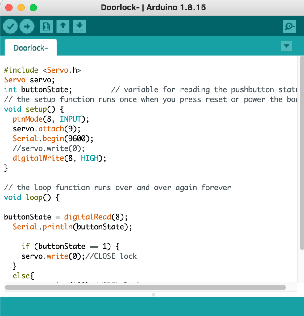
Arduino-IDE
Step 1:- Copy or download door.ino from the Github Repo.
Step 2:- Change the CLOSE and OPEN lock position as your own lock.
Step 3:- Upload it to the Arduino Pro mini.
Coding,APK, .aia, Flow
Each and every coding of the project along with the apk file that i had made using mit app inventory, is given in the github link bellow download the project and give it a try to make it by your own, it is super adventurous and fun.
After completing with the project i had gain more confidence about the IoT and app making field and knowledge about those part want to thank bolt IoT for giving me the opportunity to learn and discover the projects by my own, it’s been a great journey.
Let’s assume that you are a daily commuter and you start your journey from your home every morning. So one fine day as you reached half way it started raining. For a commuter it’s a really difficult situation if his/her attire gets disturbed because of rain. So in order to solve this problem an alert system is created with the help of BOLT IOT.
A person would argue that whats new in this project like we do have weather apps in our phone for checking daily forecast. Answer to this question lies in the working of the project. It first fetches weather data from weather api and validates various parameters to see if there are any signs of rain within the day. If it seems like raining it will notify the user with a text message sent to his phone as well as a buzzer connected to the main door will start buzzing.
A commuter’s life is all about reaching the work place on time and in such time constraining situation it’s obvious that the person won’t always check the weather on his own. In such cases this project saves the day because of its feature of running automatically scheduled at a commuter’s office going time.
Tested successfully on Mac OSX but the project is platform independent and can be executed on multiple platforms such as Windows, Ubuntu and Digital Ocean.
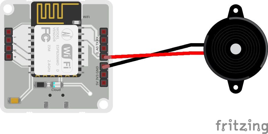
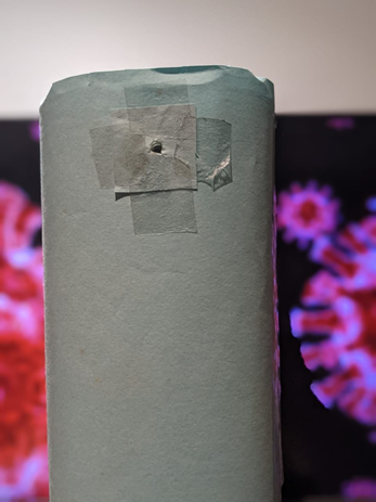
a) Take your bolt wifi module and make a connection from small pin of buzzer to GND of bolt module with the use of male female connecting wire.
b) Take another wire and connect longer pin of buzzer to A0 of bolt module
c) Give power supply with the help of usb cable.
2. Schematics –
Software Configuration And Programming:
Bolt IOT Cloud Configuration:
The process starts by first getting registered at Bolt Cloud.
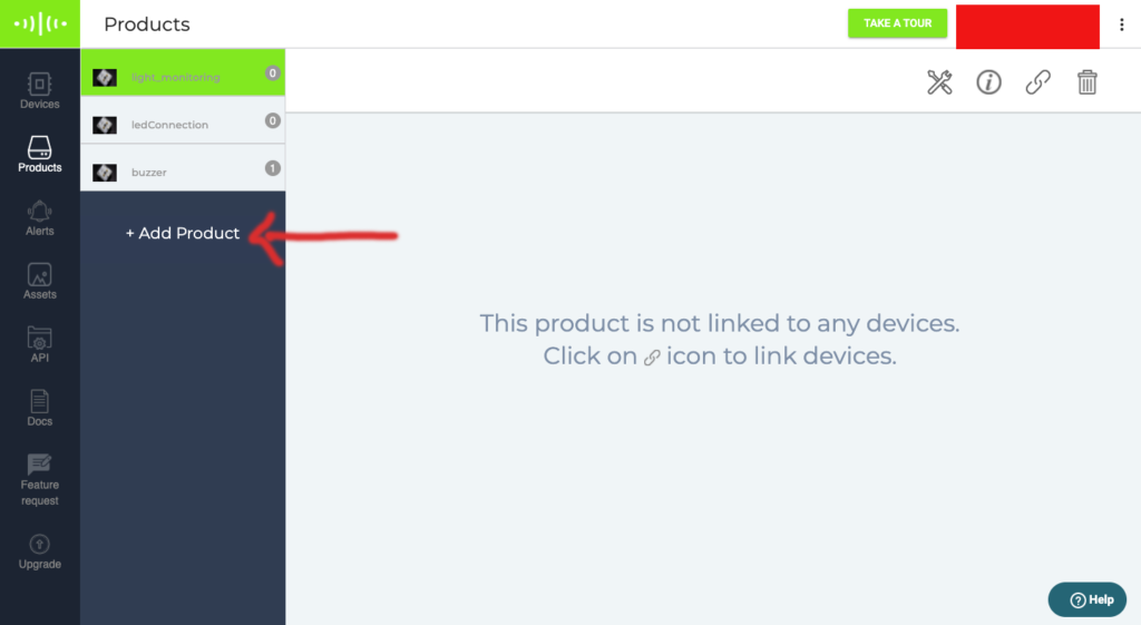
2. Now go to Products tab in sidebar and click on add product to create a product.
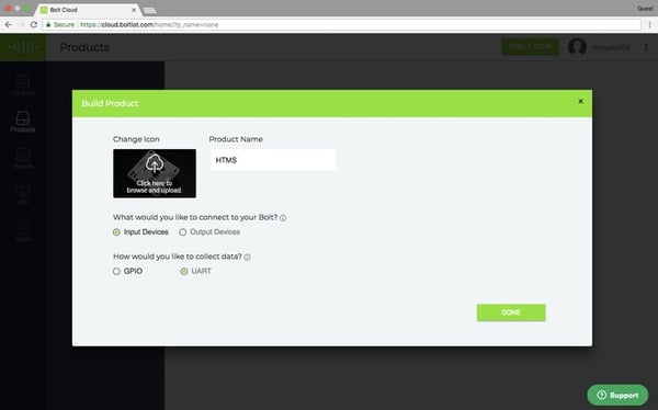
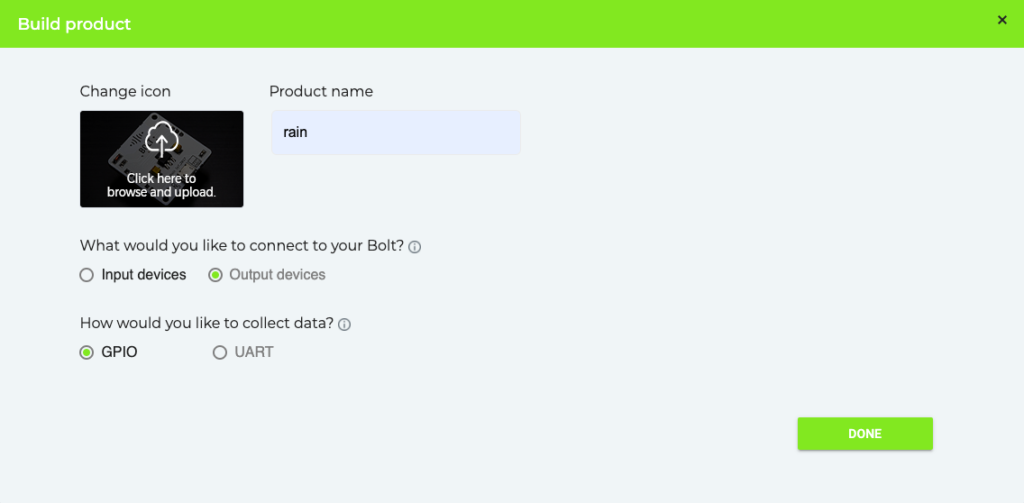
3. As soon as you will click the add product button, build product window will pop up. Enter product name and upload icon image as per your choice. Beside that select other options as shown in the image below.
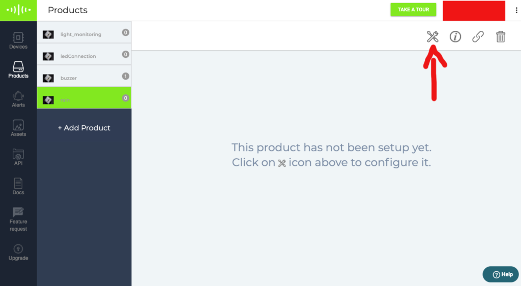
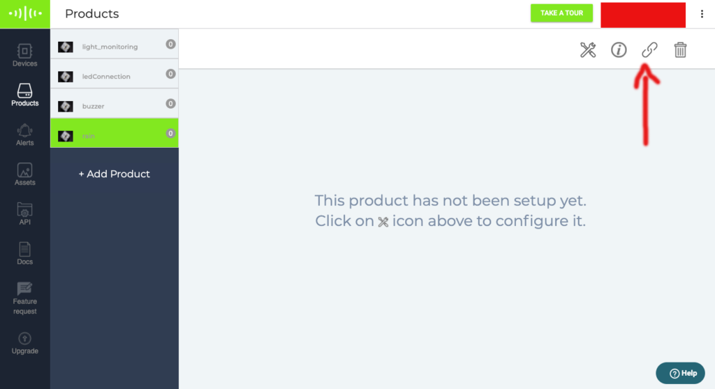
4. After product build is completed your product will be available in products tab. Select it and then select configure product as shown in the image below.
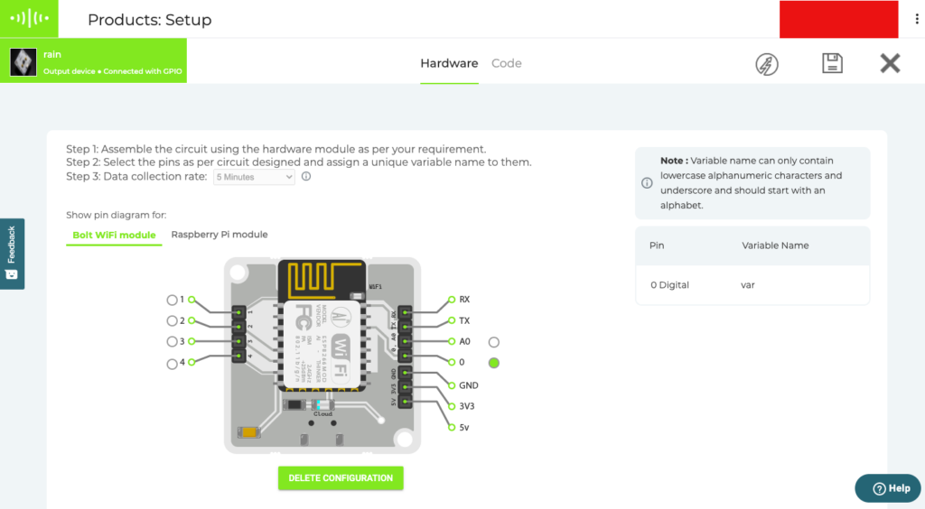
5. Here you just need to specify the design because the coding part will be carried out using bolt python library which will be later taken care of. So as you can see in the below image, you need to select a digital pin which we have selected as pin 0 for one end of buzzer and the another end is connected to the ground. As soon as the pin is selected it needs to be assigned a variable name of your choice. Beside this you can also select the data collection rate ranging from 5 minutes to 24 hours. As soon as you are done with configurations you can save it by selecting save option from top right.
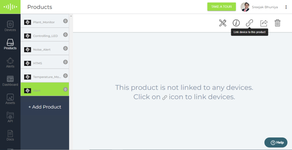
6. Now our product is ready to be linked with the bolt device.
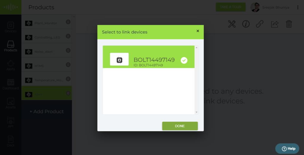
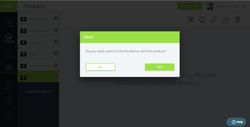
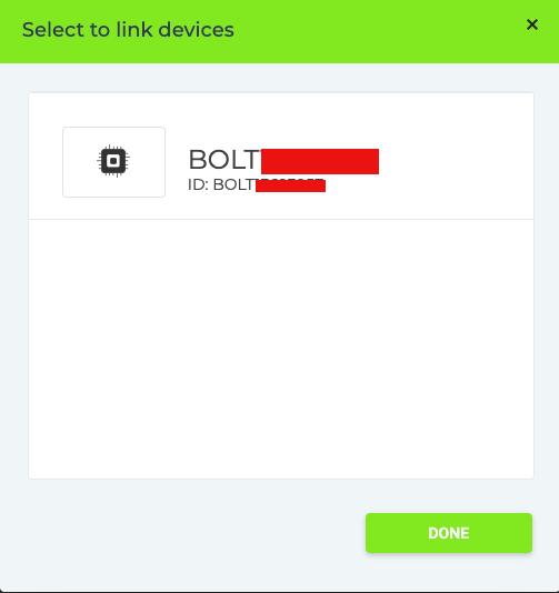
7. As soon as you click the button showed in the above pic an alert will be displayed which will prompt you to select a device.
With clicking done your product is ready being linked to a device. Now we will head towards coding part.
1.1- Adding and selecting the ESP8266 board to the IDE
1.2 – Downloading and adding necessary libraries
1.2- Coding the Sanitizer Dispenser and Temperature Scanner
2. IFTTT Setup
2.1- Getting WebHook Credentials
2.2- Creating an Applet
3. Coding the Bolt module
3.1 – Getting All the Credentials
3.2– Creating the conf.py file.
3.3- Creating the high_temp.py file
4. Schematics and Connections
4.1- PCB Designing
4.2- External Connections
5. Hardware
D) Demonstration
1. Testing the sanitiser dispenser and temperature detection.
2. Testing the calling and mail feature.
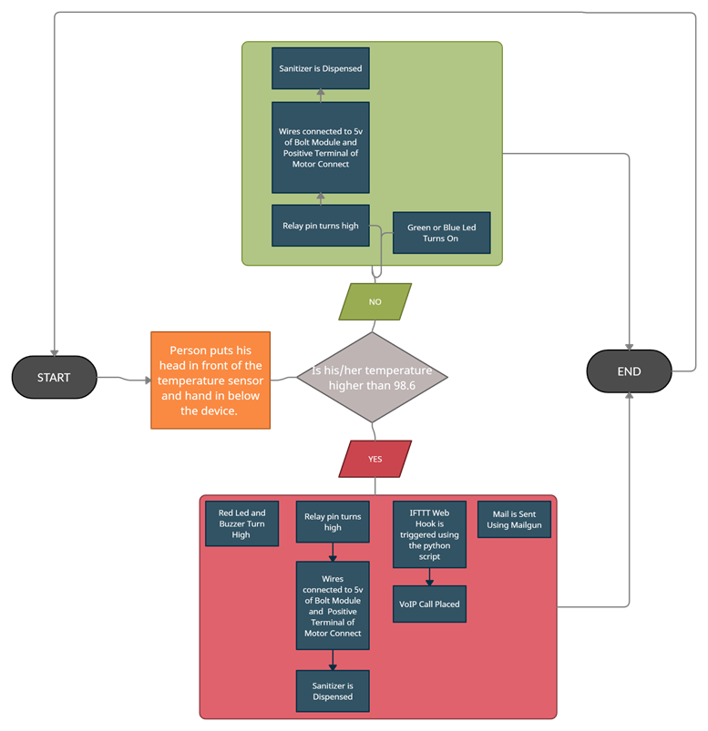
3. Flow Chart
4. Full Video
OVERVIEW
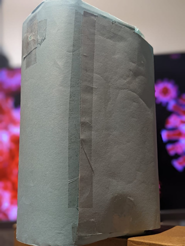
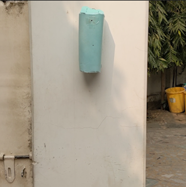
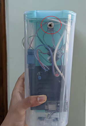
The device’s primary aim is to lower the spread of the coronavirus disease. The device checks for the person’s temperature. If it is under the usual temperature, there is a blue led which lights up indicates that the temperature is normal and the person can go. In case the person’s temperature is high, a red led lights up and a buzzer is activated to ensure that the person and the people around him are aware that he/she has a high temperature. Along with that, an automatic mail and phonecall is placed to the owner or the person in charge of the place where the device has been set up. In addition to that, the system dispenses sanitiserautomatically as soon as the person places his/her hand in front of the sensor. This prevents surface transmission, unlike the usual sanitiser dispersers.
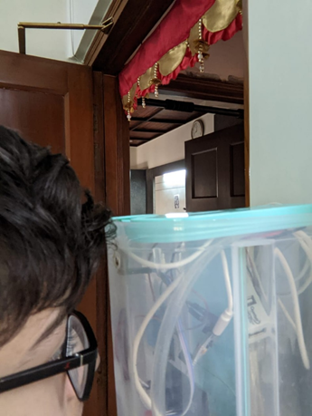
Device installed at my house’s entrance
THINGS USED IN THE PROJECT
HARDWARE COMPONENTS
Bolt IOT Wi Fi Module
GY-906 MLX90614-BAA Non-Contact Infrared Temperature Sensor
Node-MCU/ ESP8266 Board (Any Arduino board would also work)
HC-SR04 Ultrasonic Sensor
5V Submersible water pump motor
5V Relay Module
5mm LEDs – Red and Blue
Copper Wires
Jumper Wires (Male to Female, Male to Male) Female Pin Header Strip
USB A to Micro USB Cables – 2
Power Bank
1 m Plastic Pipe
Plastic Box
Custom Built PCB
SOFTWARES, APPS AND ONLINE SERVICES
Bolt Iot Android App
IFTTT
Ubuntu (Vagrant/Virtual Box)
Mailgun
EasyEDA
JLCPCB
HAND TOOLS AND FABRICATION MACHINES
Soldering Iron (Generic)
Solder Wire
Glue Gun
Hand Drill
Wire Stripper
Screw Drivers
BUILDING
1. CODING THE NODEMCU BOARD
In order to deploy our C++ code into the ESP8266 board , we need an IDE. For this, we will be using the Arduino IDE which can be downloaded from www.arduino.cc/en/software.
1.1 – Adding and Selecting the ESP8266 Board in the IDE
Before we jump on to coding the board, we need to make sure that the board is recognizable by the IDE. If you are using an Arduino board, you can skip this step but if you are using an ESP 8266 board, you will need to add it in the IDE. In order to do that, open the IDE and click on File >> Preferences and in the Additional Boards Manager URLs, add these 2 links separated by a comma: http://arduino.esp8266.com/stable/package_esp8266com_index.json
Until now, we have just added the URLs for the boards in the boards manager. To proceed further, we need to install it in the IDE. To install it, we first need to go to the Boards Manager by clicking on Tools>>Boards>>Boards Manager
Inside the Boards Manager, we need to search for esp8266 and install it. Once we do that, we need to select the correct board. In our case, it is the NodeMCU 1.0 board. To select it, go to Tools>>Board>>ESP8266 Boards >> NodeMCU 1.0
1.2- Downloading and adding necessary libraries:
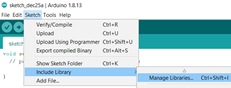
It is not only the board which needs to be recognized. We are using 2 additional sensors which are the ultrasonic sensor and the temperature sensor and we need to make sure that the board is able to communicate with it. For that, we need to install their libraries. The library for the Adafruit MLX90614 Temperature Sensor can be installed from the IDE itself. We need to go to Sketch>>Include Library>>Manage Libraries. In the Library Manager, search for the sensor and install its library.
Next, we need to install the library for the Ultrasonic Sensor. This library by Erick Simoes makes it really easy to use the sensor. Firstly, open THIS LINK and it would install a zip folder of the library into your system.
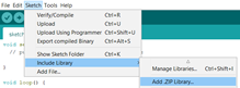
Then go to Sketch>>Include Library>>Add a .ZIP Library. Then an explorer window will open. Navigate to the location when the zip folder has been installed and select it.
1.3-Coding the Sanitizer Dispenser and Temperature Scanner:
Well, I guess this is the part you were waiting for. I am going to explain the code part by part . Please do pay attention to the comments in the code as well.
So firstly, before the setup function, we need to import the libraries and declare the pins and variables. That’s what we are doing here.
/* IMPORTING THE LIBRARIES */
#include <ESP8266WiFi.h>
#include <Wire.h>
#include <Adafruit_MLX90614.h>
#include <Ultrasonic.h>
/* DECLARING THE VARIABLES */
int distance; //variable to store distance measured by the ultrasonic sensor
float temp_f; //variable to store the temperature

/* NAMINGS THE PINS AS PER THE OBJECTS CONNECTED TO IT */
#define triger D3 //the trigger pin of the ultrasonic sensor
#define echo D4 //the echo pin of the ultrasonic sensor
#define boltpin D6 //pin connected to pin 0 of bolt iot module
#define relayofmotor D5 //Pin connected to the relay which will help in acivating the motor
#define greenled D7 //the led which I want to glow when the temperature is low
#define buzzerandredled  D8 //the pin which is connected to the red led and the buzzer which is want to activate of the temperature is high.
/*DECLARING THE SENSOR OBJECTS*/
Ultrasonic ultrasonic(triger, echo); //Creating an ultrasonic sensor object with the trigger and echo pins as the parameters
Adafruit_MLX90614 mlx = Adafruit_MLX90614();//creating a temperature sensor object
One question which might come up to your mind is that why have we declared the temperature variable as a float and not an integer. Well, it is because float is a datatype which can even store decimals unlike an integer. Because most of the times the temperature is a decimal number, I have used a float instead of an int.
Next, we move on to the setup function. All the code in the setup function is just run once in the start. This is where we declare of the pins are output or input and also do other basic things like starting the sensor.
void setup() {
  Serial.begin(9600);//Starting the serial monitor at 9600 baud
  mlx.begin();//starting the sensor
  /* DECLARING THE OUTPUT PINS */
  pinMode(relayofmotor, OUTPUT);
  pinMode(boltpin, OUTPUT);
  pinMode(greenled, OUTPUT);
  pinMode(buzzerandredled, OUTPUT);
}
Now we move on to the loop function. The code inside this function continuously runs.
void loop() {
  distance = ultrasonic.read(); //Stores the distance in cm  measured by in ultrasonic sensor in the variable
  temp_f = mlx.readObjectTempF(); //Stores the temperature in fahrenheit measured by in temperature sensor the variable
  if (distance<8){ // This set of code will run if the distance is less than 8 which means someone's hand is below the device

      if (temp_f>98.6 and temp_f<1500){ //person is in front of the sensor and temperature is higer than usual. Errors are also avoided as if the temperature value is 1500, it means there is an issue with the sensor.
      digitalWrite(boltpin, HIGH);
      digitalWrite(relayofmotor, HIGH);
      digitalWrite(buzzerandredled, HIGH);
      delay(1000);
      digitalWrite(relayofmotor, LOW);
      delay(1000);
      digitalWrite(buzzerandredled, LOW);
      delay(11000);
      digitalWrite(boltpin, LOW);
    }
    if (temp_f<98.5 and temp_f<1500){ // person is in  of sensor but temperature ok
    digitalWrite(relayofmotor, HIGH);
    digitalWrite(greenled, HIGH);
    delay(1000);
    digitalWrite(relayofmotor, LOW);
    delay(10000);
    digitalWrite(greenled, LOW);

  }

}
}
In the set of code above, firstly I have stored the values of the distance and temperatures in their respective variables. I have done it in the loop and not the setup function because I want them to be updated every time.
You might have noticed that I have made use of the if conditional many times. This is because I want a separate set of actions to be performed depending on the response form the sensors. So firstly, all the code in the loop function is surrounded by an if conditional which checks if the person’s hand is below the ultrasonic sensor. This means that if the distance is less than 8cm, then the rest of the code will run otherwise it will not.
Then comes the first conditional. It is when the temperature of the person is higher than 98.6 degree AND lower than 1500 degree. In this case the pins for the redledandbuzzer, the relay for the motor and the bolt turn high and then low after a specific time.
On the other hand, if the person’s temperature is below 98.6 degree, only the sanitiser dispenses and the green led glows for which the pins for the green led and for the relay turn high and then low.
You would be having 2 possible questions here. Firstly, you might ask that why have we added that second conditional that the temperature is below 1500.It is because if there is any loose connection or short circuit in the sensor, it sends the value 1500. So just to make sure that the device does not falsely determine someone to have a high temperature, I have added this conditional.
Secondly, you might be wondering what this boltpin is but don’t, I’m going to explain it to you as well. So what I have done is that I have connected the D6 pin or the boltpin of the NodeMCU to the pin 0 of the bolt iot module. I have done this because I am also running a python script on the Bolt IOT module and I have programmed it in such a way that when the pin 0 of Bolt Module is high, a mail will be sent along with a call to a specified individual. In the steps below, I’m going to show and explain how can we set up those automated calls and emails.
2. IFTTT SETUP
IFTTT stands for If This Then That and it is a very nice online service which will help us in this project. So Before we proceed, we first need to create an account on IFTTT and we can do that by heading over to https://ifttt.com/. Also, as we will be using the VoIP Calls facility, we need to have the IFTTT app installed on our smartphone. It can easily be installed from Play Store on Android and through the App Store for IOS.
2.1 Getting the WebHook credentials:
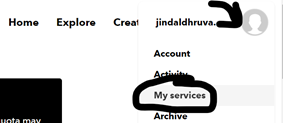
Before we create an applet, we need to get our IFTTT webhook credentials. So basically, Web Hook is a service will allows us to integrate services offered by IFTTT with our Bolt Module. I will explain its working in the next step. For now, let’s get out credentials. To do that, click on the Profile Icon on the top right on click on MyServices. Scroll down and click on WebHooks and then click on Documentation in the top right.
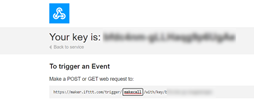
In the documentation you would get a unique webhook link for your account. Make sure that you don’t share it with anyone. In the link, you would see a parameter named event. You can set it to anything but in my case , I’m gonna call it makecall. Now copy the entire link and keep it safe as this is the link which we will call to trigger the webhook and place a call.
2.2 Creating the Applet
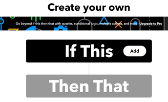
To create an applet, click on Create on the top right of the page. IFTTT works on the principle of IF THIS THEN THAT. It means if this happens then do that. So in our case the thing which is happening is the webhook being triggered with bolt’s pin 0 is high and when it happens, we want to place a VoIP Call.
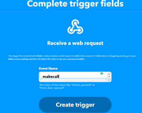
So to do that, click on If This and search and choose Webhooks. Next, there is 1 option and that is Receive a web request and we select it. Now we have to enter the event name which we chose in the previous step. So in my case, it was makecall. Then, click on Create Trigger.
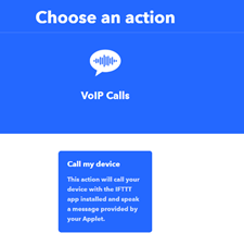
So now we want to select an action which is triggered as soon as the webhook is called. For that, click on Then That and select VoIP Calls. Then select call my device . After that if you get an option to connect your device , please do so by clicking on the connect button.
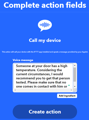
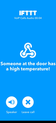
Next, we get an option to set the text which will be said during the call. You can set it to whatever you like. Just to try it out, enter the URL which we got to trigger the webhook in any browser. Within seconds, you would get a phone call on your phone and when you pick it up, you would be able to hear the voice message.
3.CODING THE BOLT MODULE
Now in this section, we will be seeing how the device is able to perform the best and most useful functions of placing the call by calling the IFTTT webhook and sending automated emails using Mailgun.
3.1 Getting all The Credentials
Before we start uploading code onto the Bolt Module , we should collect all the required credentials.
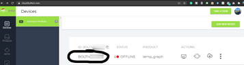
a) BOLT CREDENTIALS: There are 2 credentials which we need to connect to out bolt module and those our the API KEY and the DEVICE ID. To find them, head over to https://cloud.boltiot.com/ and you
would see the device ID in the dashboard. It would be something like BOLTXXXX. Next, on the left panel, you would find an API button. Click on it and then copy your API Key. Copy both of them and save it somewhere.
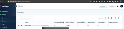
B) MAILGUN CREDENTIALS: We will be using an online service named Mailgun for sending the automated email. Firstly sign up or login by heading over to https://www.mailgun.com/. Then start off by creating a sending domain. Once you have done that, go to Sending>>Do mains and click on your sending domain. Firstly you would see your Sandbox URL which is something like sandboxXXXX.mailgun.org. Your sender email is test@yourSandboxURL.
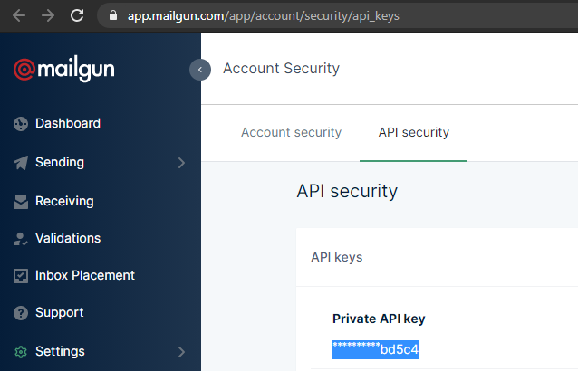
To find your Mailgun API key, click on API Keys on the right. Then you would be redirected to a page where you would be able to see your API key. From there, copy your private API key.
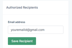
There is just 1 last thing and that is to Add Recipient. Mailgun does not allow sending emails to an email address until and unless you verify it first. To do so, go back to the sender page and on the right hand side, you would get an option to Save Recipient. An email would then have been send by Mailgin to the email address you provided to verify it. Once you do so, your email address would become a verified recipient.
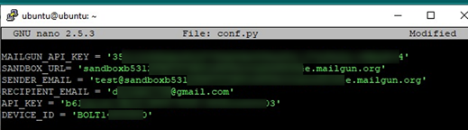
3.2 Creating the conf.py file
Firstly, open set up a virtual machine and run ubuntu on it. We are creating a file named conf.py and it will store all the credentials we got from the previous step. To create the file, type nano confy.py and hit enter. Inside the file, enter all the credentials in this manner:
Once you have done that, click CTRL + X and then Y to save and exit.
3.2 Creating the high_temp.py file
As before, we will create a new file using nano high_temp.py. Before I show you the code, let me explain to you what we expect from it. Firstly, what we want is that the code gets the status of the pin 0. We know that if the person has a high temperature, the D6 pin of the NodeMCU which is connected with the digital pin 0 of the Bolt module turns high. So if the status is high, we want to send an email using mailgun and also make a web request which places the call via IFTTT. Also, also want to print the response for troubleshooting cases.
Here is the code:
# IMPORTING THE LIBRARIES
import requests ##library which will help in making web request
import conf # the file with all the credentials
from boltiot import Email, Bolt #Bolt Iot libraries
import json, time #Other libraries which we will need
mybolt = Bolt(conf.API_KEY, conf.DEVICE_ID) # establishing connection with the bolt module
mailer = Email(conf.MAILGUN_API_KEY, conf.SANDBOX_URL, conf.SENDER_EMAIL,conf.RECIPIENT_EMAIL)#creating the mailer object
while True:
response = mybolt.digitalRead('0')#Pin high when high temperature and pin low when low temperature
data = json.loads(response #Loading the data
decision = data['value'].rstrip() # decosion will be 1 for high temperature and 0 for low temperature
if decision == "1": #if person has high temperature
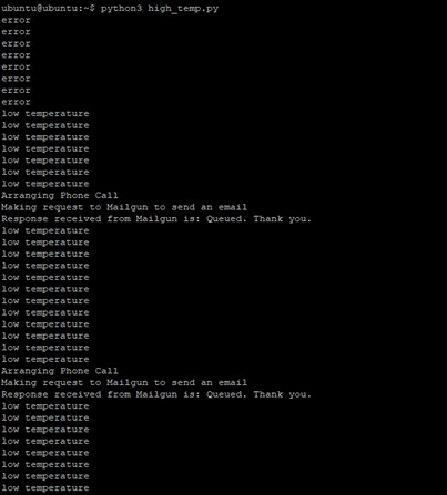
print("Arranging Phone Call")
r= requests.get("http://maker.ifttt.com/trigger/makecall/with/key/lC5kvr7aPRfsnzUe6diZygd7vthmOn0Oa530qvbw-lm") #Calling the webhook
print("Making request to Mailgun to send an email")
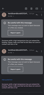
response = mailer.send_email("Alert!", "Someone whith a high temperature has just entered the building.") # ("Subbect", "Body")
response_text = json.loads(response.text)#response from mailgun
print("Response received from Mailgun is: " + str(response_text['message'])) #printing the response for troubleshooting purpouses
elif decision =="0":
print("low temperature")
else:
print("error")
time.sleep(4)#code executes again after 4 seconds.
4.SCHEMATICS AND CONNECTIONS
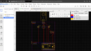
4.1 – PCB Designing
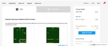
When I was finished with building the initial prototype of this product, it worked properly but it would not have for long due to the ton of connections which could become loose and come out at any moment. That’s why I decided to try my hand in PCB designing.
I used an online website named EasyEda to make design the PCB and then gave it order to JLCPCB. Once the PCB had arrived, I soldered most of components onto it and for the rest, I soldered female header bug strips and then attached the components later.
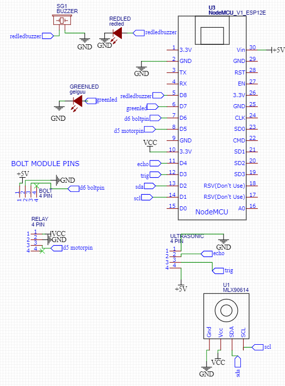
This is a schematic of the PCB:
PS: Instead of connecting the pins in the schematics, I have added net ports so that it is neater and easier to understand.
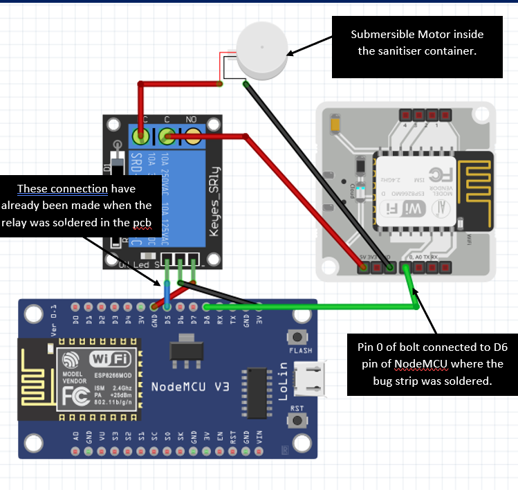
4.2 External Connections:
The above schematic is just of the PCB and of the pins which would be attached to it. There were also a few more connections left for which I am making a diagram below. Please note that the below connections are the external ones, the rest of the connections have been implemented into the PCB.
In the above schematic, I have shown the external connections.It is mainly the connection between the bolt module, relay and NodeMCU. The 3 input pins of the relay had been soldered in the PCB. Now when the replay turned high, I wanted the submersible motor inside the sanitiser container to work. So I connected the Ground of the Motor to ground of the Bolt Module. The 5v of the motor was connected to NC of the relay which is stands for normally closed and the 5v of the Bolt Module was connected to the COM port of the relay. In this way, whenever I programmed the relay to become high, the motor turned on.
5. HARDWARE
There were a few parts whose placing plays an important role. I just wated to show them to you as well.
MOTOR:
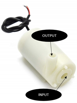
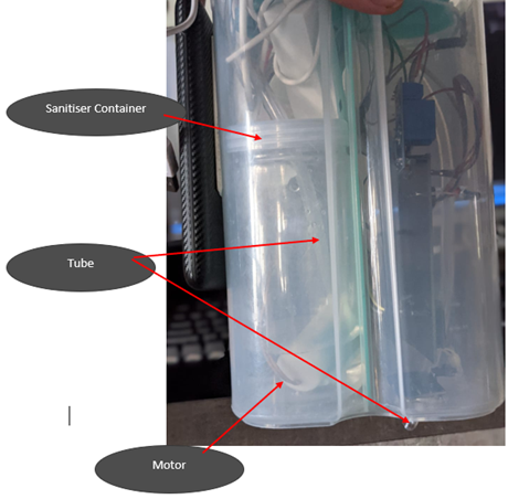
The motor was placed inside of a container filled with sanitiser. As it was submerged completely in sanitiser, it could take the sanitizer through the input hole. And on the output hole, I attached one end of a plastic tube and the other end is attached to the bottom of the enclosure near the ultrasonic sensor. This is how I have placed the motor in the project:
The container contained sanitizer which is alcohol based. This means if the top of the container is not covered, all the sanitizer would evaporate. To prevent that, I put the cap of the container on it and made 2 holes, 1 for the tube and the other for the 2 wires.
ULTRASONIC SENSOR:
The Ultrasonic sensor has been placed at the bottom of the device and next to the hole made for the plastic tube. So now, when the user places their hand below the device, the ultrasonic sensor detects their hand and the sanitiser is immediately dispensed right there. I used a hand drill to make holes in the bottom and make way for the ultrasonic sensor.
TEMPERATURE SENSOR:
I have placed the temperature sensor at the top of the device so that the user does not have to bend to get his/her temperature scanned. I used a hand drill to make a hole for the sensor.
DEMONSTRATION
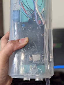
Before I start testing, I have uploaded the code on the nodeMCU board with the Arduino IDE, run the python script on my laptop and lastly connected the device with a power bank.
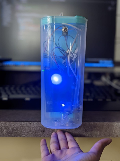
1.Testing the sanitiser dispenser and temperature detection.
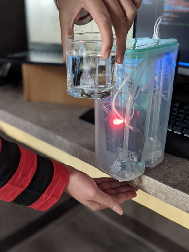
In order to check if the temperature sensor and the sanitiser dispenser were working properly, I used the ambient room temperature in one case and a hot glass of water to stimulate the high temperature. The results were exactly as expected. In the first case, the blue led lit up and the sanitiser was dispensed and in the second case, the buzzer and red led were triggered along with the sanitiser dispensing.
CASE 1:
CASE 2:
2.Testing the Mail and Calling Feature.
To test if these 2 key features were working , I ran the python script on my laptop. I first checked the terminal as the status was being printed there.
This is how the terminal looked like. It showed error in the starting because the device wasn’t powered on.
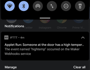
This is the automated notification which was sent on the phone by IFTTT.:
This is the automated mail which was sent:
And lastly, this is the call which was placed.
3.Flow Chart
I also wanted to show you the entire flow of the project in case you had any confusions.
4.FullVideo
If you want to see this entire project in action, click HERE .
Busy readers take note in few minutes , you will be acquainted with knowledge to run your code on above machine which is operating at 4 K and your message will be unhackable or quantum secured . Super Cool!
Introduction
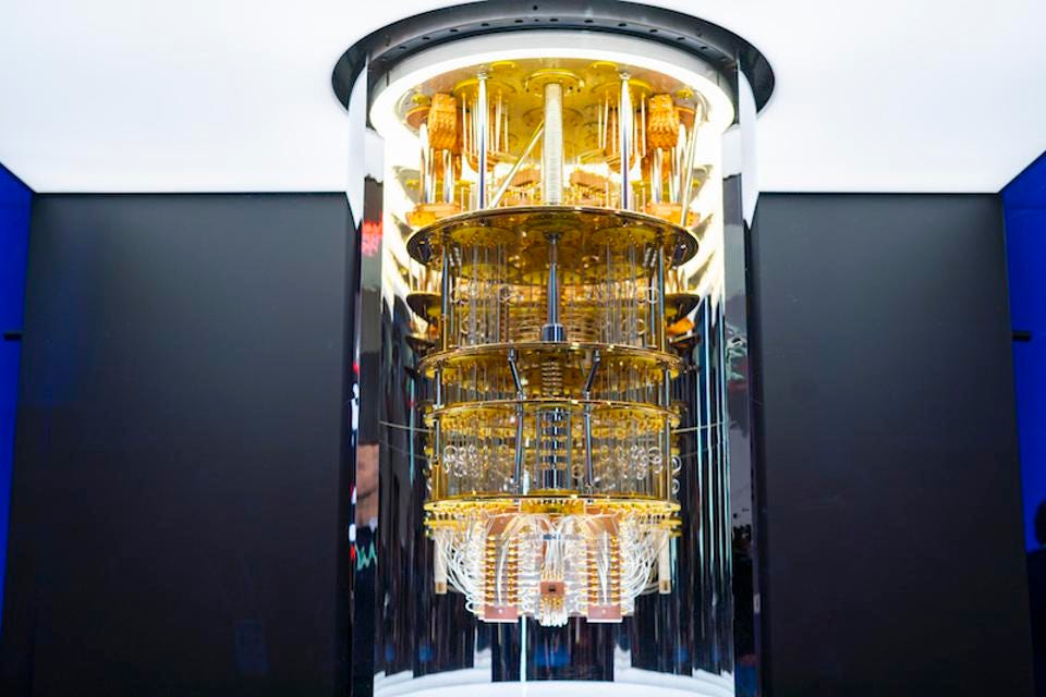
Gate of a Superconducting Quantum Computer
Quantum Computers are not far from our daily lives. Today or tommorow we all using one or other form(Why?). Quantum computers not only exploit Quantum Mechanics (Superposition and Entanglement) but also an answer to rusting Moore ‘s Law.
Quantum Computers exploit quantum mechanics but we can’t expect normal users to learn dirac notation first.Quantum protocols which are inherently unhackable(Non-cloning theorem) should be made user friendly.
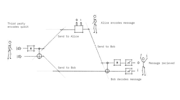
Superdense Coding
Superdense Coding is one of the famous quantum protocol .In few minutes you will be implementing it.
I already said you need not to learn Quantum Mechanics to understand things(you can visit caption link).
Basically we have 3 person , Charlie , Alice ,Bob. Now , alice wants to talk to bob. She wants secure channel . Thanks to its newly read blog on unhackable internet .She decided you use that .She went to charlie (a physicist ) about it . He told her about Quantum Channels .But like you she does not understand it .Charlie used 2 LEDS to make her understand it .
Let us see How?
1)Step1: Entanglement Qubits
2)Step2: Encoding the message
3) Step3:Measuring the Qubits
4) Step4: Decoding the message
I am skipping 1) and 3) steps as they involve knowledge of Quantum Mechanics and qiskit. For more advanced reader please check my repo (at the end)
Things used in the project:
Hardware
1) LEDS(2)
2)330 ohm Ressistors(2)
3)Breadboard and 3 male-male jumpers
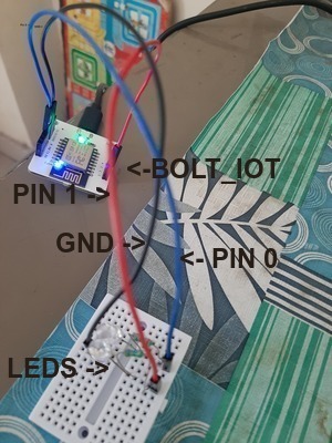
4)BOLT IOT module
Software
1)boltiot 1.11.2
2)qiskit 0.36.1
3)matplotlib and their dependencies
4)Python version=3.9.7
Do connections as shown in the image:
circuit photo
Encoding
Encoding Message: As you all know Computers only understand binaries or 1,0s. We will also encode our message in binary.
I have used digital electronics convention. Pin=1 as most significant bit (msb) and Pin= 0 least significant bit(lsb). You can your too.
Now we represent 2-bit (msg) using LEDs. LED is ON means “1” otherwise “0”.
Now Alice transmitted the encoded message. It is turn of Bob
Bob will also follow same procedure:
Note that : I have used received_ message as due to noise alice message may change .
Conclusion
Congratulation! You have implemented Superdense Coding Protocol using BOLT. I have used one BOLT Device both reciving and transmission . I highly recommend you to use 2 devices and learn qiskit for implementing it and getting real feel.
This blog provides you with guidelines on how to format your Project Submission. Following these guidelines will improve your chances for getting your project published on the Bolt IoT projects page here.
So let’s get started.
To write a Project Blog, you must first Create the Project Blog. And for that, go through the following steps.
Step 1: Login into the project submission site
To login into the project submission site, click on this link,
It will redirect you to the Bolt Cloud login page.
3. Now enter your login credentials of Bolt Cloud and in case you have used your google account to login into Bolt Cloud then click on Sign in with Google button. 4. After successful login, you will be redirected to the project submission admin dashboard. 5. In case you are already logged in to your Bolt Cloud account then just by clicking on this link, you will be redirected to the project submission admin dashboard.
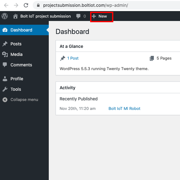
Step 2) Creating Post
Check on “+Post” button just below that address bar. A new blog will be created, and you can start editing it.
Your Blog should contain the following.
Title
The title show up at the top of the page. The title of this Blog is “Submitting a project”. Add a catchy title that describes your project and also encourage the user to click on it. For example :
5 minutes, 4 steps and “Ok Google turn on the lights”
Sanitize to fight COVID-19 using Bolt IoT
Smart Door with Face Unlock using Bolt IoT
The title should be a minimum of 30 characters and a maximum of 50 characters. You can use https://www.lettercount.com/
Cover Image
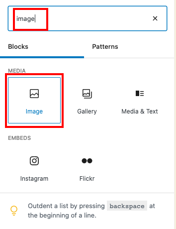
At the start of the project blog, add a cover image that describes your project. Ideally use a photo of the project or a screenshot if it’s a digital output. The following images show how to add an image.
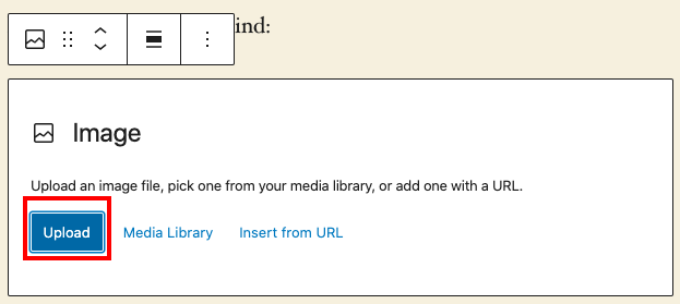
Click on the + button on the top left corner.Type “Image” in the search box, and under media, select imageClick on the upload button, and then select the image you want to upload
Keep the following in mind:
Do NOT use GIF
Do NOT use images from the Google search or other sources where you do not own the rights to it.
Cover image sizes should be of 300px high and 400px wide.
Story/problem
Why are you making this specific project, what problem are you trying to solve. The story/problem section explains this.
Don’t add story/problem as a heading.
The story should be of maximum 3-4 lines.
Things used in this project
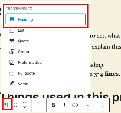
This is the first section which will have a heading. Use the line “Things used in this project” with the type Heading, and select H2 as the formatter.
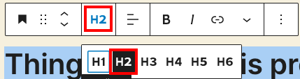
Click on the heading you have add, select the format type icon, and select heading.
Once you select heading, click on the heading subtype and select H2
Hardware components
Next as the sub-heading of type h3, “Hardware components”. Here you will add the details of the hardware components that you have used in your project. Keep in mind, the below points while adding the hardware components. Things to remember in this section:
Add a photo of the hardware component along with the name of the component.
Embed a link in the name of the items listed unless they are included as part of the Bolt IoT starter kit or if they are commonly known.
Software, Apps and online services
The next sub-heading is the “Software, Apps and Online Services”. This is a h3 type of a heading. Add the details of the software/apps that you have used in your project. Things to remember in this section.
Add the logo of the Software or App, or the logo of the service provider.
Add the name of the software, app or service provider.
Add a link in the name of the item listed.
Hardware setup
The hardware setup text should be mentioned with the heading h2. In this section you will add details of making connections. Things to remember in this section.
Add the details about hardware connection in step-wise format.
Each step should be clearly marked as Step 1, Step 2, etc. Make sure you follow this format only.
Always add Schematics or photo of the circuit connection.
Always divide into smaller steps and do not write a big paragraph for any steps.
Where-ever required add photos to better explain what the step means.
Software Programming
The Software setup text should be mentioned with the heading h2. In this section you will write the details about software programming in a step-wise format.
Even if the software has a guided user interface (GUI), add it into the software programming section.
In case the setup is base on GUI add images to describe it.
In case you have any longer programming code to explain, then host on https://gist.github.com/ and embed the code on the blog section.
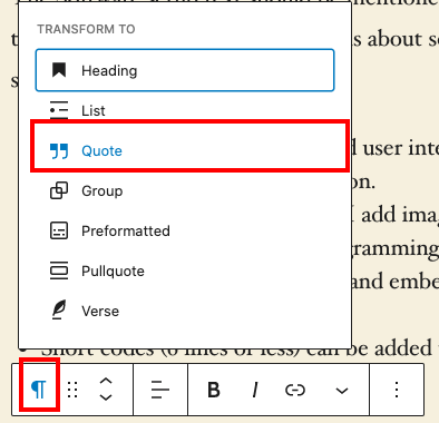
Short codes (6 lines or less) can be added to the blog directly, using the quote type of text.
This is a quoted text. Add a short description for the code here.
Write the code here.
Conclusion
Your are almost done. Add the Conclusion header in h2 heading, and then type out what you managed to achieve by doing this project.
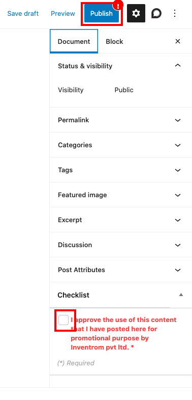
Once you have finished adding all the required details, click on the publish button on the top right corner. You might have to click on the checkbox before you can publish your post.
Next click on the “Submit for review” button which shows up.
And that’s it. You have submitted your project to be reviewed by Bolt IoT.


![CD4051 Multiplexer: Datasheet, Circuit, Pinout [Video&FAQ]](https://www.kynix.com/editor_u/pdf/20220107/CD4051-Pinout.jpg)